
Guest blogger Masoud Zarepoor from Lake Superior State University (LSSU) introduces a novel method to localize buried objects using elastic surface waves. Zarepoor has investigated this method at the Vibration and Acoustics Laboratory (VAL) with his colleague Robert Hildebrand, a mechanical engineering professor, and a group of undergraduate students.
There are countless potential applications for buried object detectors such as metal detectors. However, for nonmetal objects, such as pottery shards at an archaeological dig or a plastic-encased landmine, the metal detector is out of its element. Seismic surface waves, perhaps created by dropping a weight at the exploration site, might suit such circumstances, were we to extract the rich information conveyed by the spectra of the wave reflections from a buried object.
Introduction to Seismic Surface Waves
Seismic surface waves (also called “Rayleigh waves”) may be most familiar in the context of earthquakes. Of course, in an earthquake, seismic surface waves happen at a much grander scale than the application discussed here, but it is still important to note the properties of these waves.
In an earthquake, several different waves propagate, such as pressure or longitudinal waves, shear waves, and surface waves. Seismic surface waves are the last arriving but most powerful seismic waves in an earthquake, responsible for the greatest part of the damage. These waves arrive late in the earthquake context because they travel along the surface (rather than directly through the Earth) and at a speed markedly lower than that of the weaker but faster waves that travel directly through the interior mass of the Earth.
To fully appreciate the potential usage of surface waves for buried object detection, we must take note of two other essential features of their behavior:
- In the context of stratified media, like the earth with its soil and rock layers, the speed of these waves depends on the wavelength. To return to the earthquake example, there’s a mix of many different wavelengths in the original seismic disturbance, so the surface wave doesn’t propagate all at once but is instead spread out over time, with different wavelengths arriving at different instants and speeds.
- Although called “surface” waves, these waves do cause some motion below the surface. However, these motions weaken with increasing depth, making the “surface” qualifier still justifiable.
Particularly noteworthy is that the longer the wavelength (as measured along the surface), the slower the motions decay with depth.
The phenomenon of earthquakes may be on the scale of tens or hundreds of kilometers. For smaller scales, such as building site evaluations with a scale of meters or tens of meters, where the goal may be to determine the foundation stratigraphy and depth to bedrock, the variation of speed with wavelength (point 1 above) is of significance. The topic of wave behavior has given rise to survey methods, in which the pattern of unseen layers beneath the surface is surmised by considering what such pattern would best explain the observed speed variation; the formative such technique is called “spectral analysis of surface waves” (SASW).
Object Localization Research
Inspired by SASW as a tool for discerning stratigraphy, the team proposed that the same sort of analysis of a spectrum of measured surface waves — but now from a reflection off of a buried object and on a “near surface” scale of perhaps tens of centimeters to a meter — might help us localize that buried object (Ref. 1). The concept is illustrated in Figure 1.
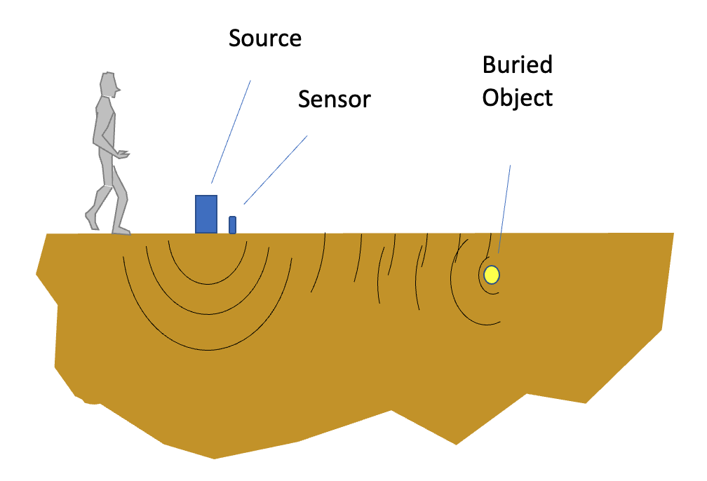 Figure 1. Concept for a near-surface buried object detection system based on surface waves.
In particular, the team assumed that certain wavelengths in the spectrum, related to the object’s depth, might be stronger than others (Figure 2). Wavelengths substantially shorter than the object depth would cause only insignificant motions at that object depth (recall point 2 above) and thereby contribute little consequent reflection. Those much longer than object depth may also be weakly reflected, simply because the object would be too insignificant of a feature compared to the scale of the wave. As for midsized wavelengths, where the wave reaches deep enough to “see” the object but not vastly deeper than it, a peak might occur in the reflected spectrum. The wavelength (or frequency) of this peak would, if the supposition is correct, serve as an index of object depth.
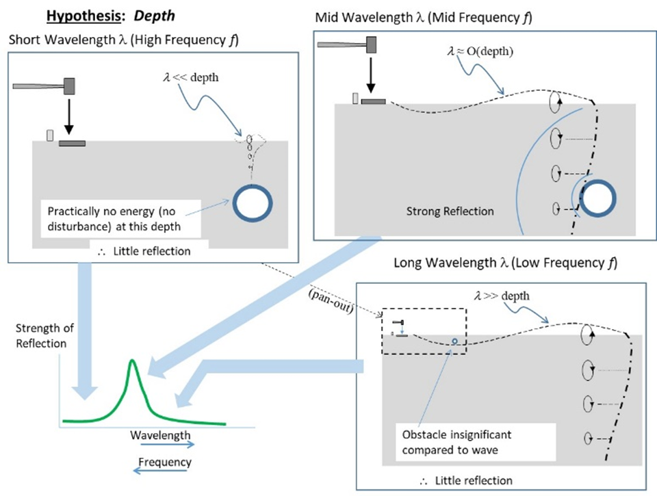 Figure 2. Illustration of the method for depth inference (reproduced from Ref. 1).
More familiar localization methods, such as echo return time for determining range (using sonar, for instance) and beaming the surface waves into preferred directions to give the azimuth, could complement the depth inference above and yield an object location in a cylindrical coordinate system. These methods remain untested but plausible suggestions to complete a localization methodology. The depth determination, however, as the least conventional and most uncertain part of the envisioned method, warranted special attention: As a first step to testing its feasibility, the team turned to simulation with the COMSOL Multiphysics® software.
COMSOL Study of Depth Inference
A homogenous medium with a free top surface, and a nonreflecting bottom and side boundaries, was created as a rough representation of a near-surface volume of uniform soil. Figure 3 shows this homogenous 2D medium that is created and meshed with triangular elements in the COMSOL Multiphysics® software. In this 2D representation, a void was provided close to the surface, at about three-quarters of the span from left to right; this void serves as the buried object, and the reflections from the object are to be used to test the depth inference. Near the far left of the top surface, surface waves are generated by a point force cycled several times at a carrier frequency, and the amplitude of these waves are modulated into the form of a pulsed envelope. The pulse is short enough that it is completed long before any reflection returns from the void, so the reflection can be clearly separated from the outgoing wave (see Figure 4).
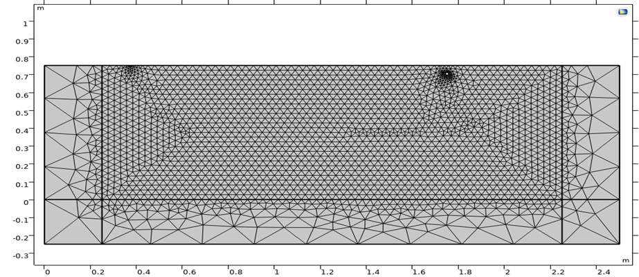 Figure 3. The mesh in COMSOL® representing a volume of Earth with a void (right side, near surface) and an excitation source (left side, near surface) (reproduced from Ref. 1).
Figure 4, obtained using the COMSOL® model, shows a surface wave pattern reflecting from the void, for a surface wavelength close to that giving peak reflection. Figure 5, for contrast, shows the situation of a much shorter wavelength excitation, mostly passing above the object, but interaction with the object is minimal, giving minimal reflection.
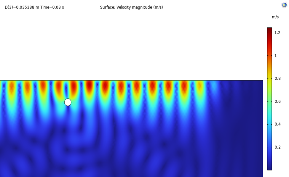 Figure 4. The reflecting surface waves near the optimal wavelength (reproduced from Ref. 1).
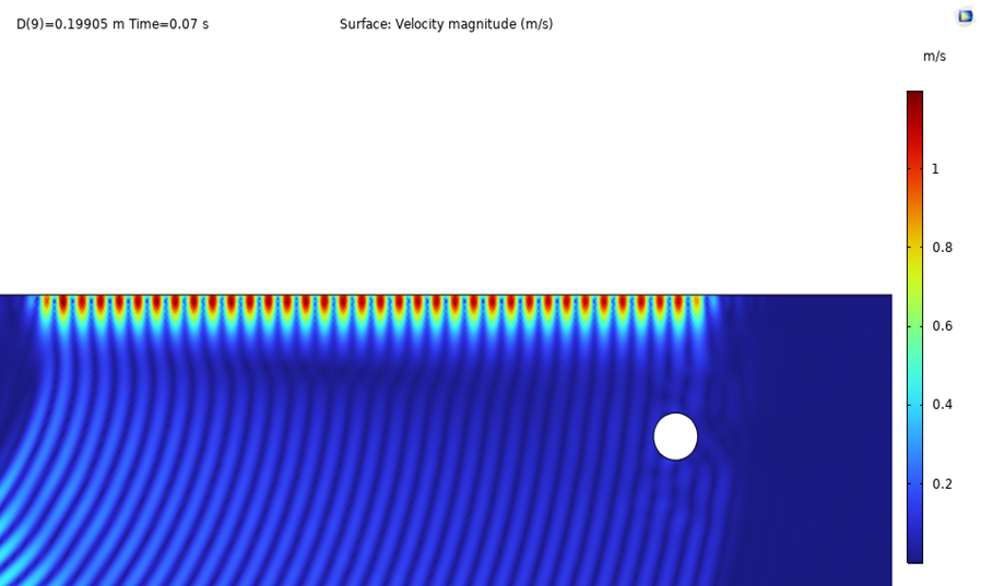 Figure 5. The minimal reflection from a shorter-wavelength excitation (reproduced from Ref. 1).
In either of the figures above, a measure of the strength of the reflection can be obtained. These can be compared for a variety of wavelengths to depth ratios, as seen in Figure 6, which was made in MATLAB® using data exported from COMSOL® simulations. Presumably, observing the wavelength at which a peak lies, in a field case, could lead to a best estimate of the object’s depth. The results confirm this supposition, with a ratio around 0.7 at which the reflection is maximal.
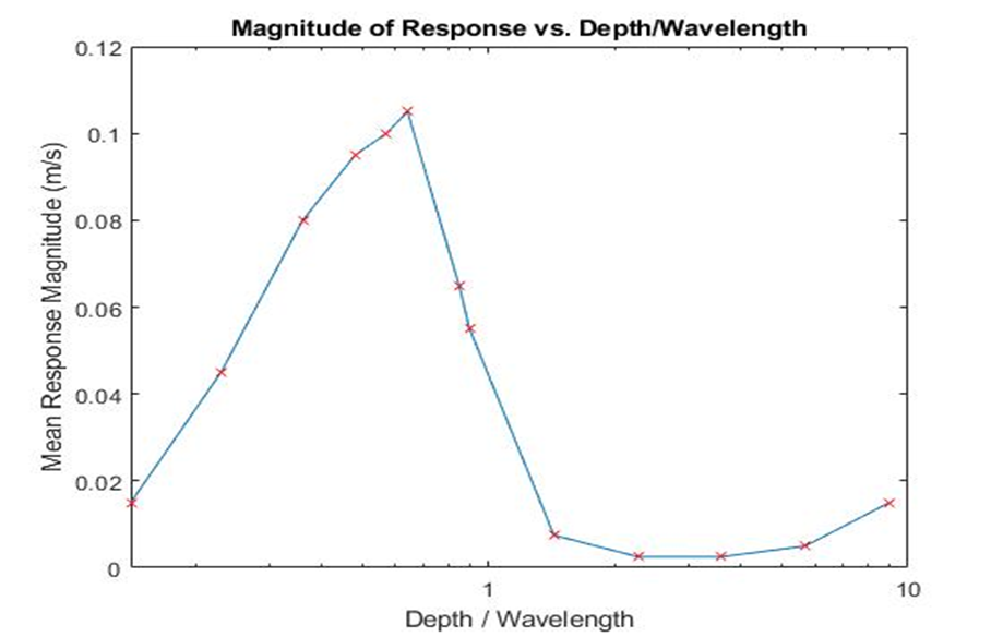 Figure 6. The strength of the reflection as a function of wavelength relative to object depth in MATLAB® (reproduced from Ref. 1).
As suggested earlier, the remaining cylindrical coordinates (range, azimuth) could be found by using conventional methods, such as by finding the echo return time of the pulse (for range) and beaming the pulse to maximize the amplitude of the reflection (for azimuth).
Simulation in COMSOL®, as discussed here, enabled the team to relate the frequency of peak reflectivity to the depth of the buried object. The team has plans to take this work further, such as by performing scale model validations at frequencies from about 10 to 100 KHz in order to obtain very short wavelengths in modestly sized scale models. In that same context, the team also plans to incorporate the proposed methods for determining azimuth and range to complement depth as illustrated here. In addition, field measurements will be conducted to test the robustness of the method in real-world conditions deviating from the ideal.
Further Reading
If you’d like to learn more about seismic waves, you can check out the following blog posts and models:
- Happy Birthday, Inge Lehmann
- Propagation of Seismic Waves Through Earth
- Ground Motion After Seismic Event: Scattering off a Small Mountain
About the Author
Masoud Zarepoor is an associate professor of mechanical engineering at Lake Superior State University. His research areas are mainly focused on vibration, smart materials, nonlinear dynamics, and acoustics. He received his PhD from Old Dominion University. He joined LSSU in August 2016, where he has been teaching and conducting research in the areas of vibration and acoustics. He introduced COMSOL Multiphysics® to LSSU engineering students after becoming familiar with it during his graduate studies. Engineering students at LSSU have been using COMSOL® in their research and courses for a wide range of applications, including acoustics studies, structural and modal analyses, and CFD simulations.
Reference
- D. Baumann et al., “Buried Object Localization by Spectral Analysis of Surface Wave Reflections”, 186th Meeting of the Acoustical Society of America and the Canadian Acoustical Association, Ottawa, May 2024, paper 4pPA5; https://pubs.aip.org/asa/poma/article/54/1/045002/3308041/Buried-object-localization-by-spectral-analysis-of
MATLAB® is a registered trademark of The MathWorks, Inc.


Comments (0)