

Granular materials are used in processes such as pharmaceutical dosing, food handling, and bulk powder transport. Their behavior depends on grain properties, contact interactions, and operating conditions. The Granular Flow Module add-on to the COMSOL Multiphysics software uses the discrete element method (DEM) to simulate individual grains and their interactions with other grains and equipment surfaces. In this blog post, we will provide an overview of the functionality in this module by highlighting various tutorial models of different industrial processes that involve granular flow.
1. Grain Packing
Industries such as agriculture, food & beverage, and pharmaceuticals involve grain packing. Packing fraction — the volume occupied by the grains divided by the total sample volume — depends on grain shape, size, and interaction forces. Understanding how these factors affect packing efficiency after the container is sealed is important for the safety of the product and the optimization of packaging processes.
The first tutorial model we’ll highlight demonstrates how grains settle under gravity to form a packed bed. The model geometry consists of a rectangular box with a length and width of 0.2 mm and a height of 0.3 mm. In the box, 5000 grains are released, with the diameters of each grain being drawn from a normal distribution with a mean of 10 μm and a standard deviation of 2.5 μm. The grains are allowed to settle under the influence of gravity and the study’s specified contact forces for 8 milliseconds.
Three contact force models are used to study the effects of different forces on the packing efficiency of the grain:
- Hertz–MD, one of the most common force models used in discrete element method (DEM) simulations
- Hertz–MD with adhesion, which extends the Hertz–MD model with surface adhesion, allowing tensile forces to prolong contact after a collision
- Hertz–MD with adhesion and van der Waals forces, which extends the previous force model by adding the (noncontact) van der Waals forces between grains, which is important when grain sizes approach the micron scale
Comparing these force models illustrates how adhesive interactions affect the predicted packing fraction.
To reduce the computational cost of these simulations, the Granular Flow interface uses a no binary search (NBS) algorithm to identify potential grain–grain contacts and an octree search algorithm to identify potential grain–wall contacts in 3D. These algorithms limit the grains and wall elements checked for each grain during the time-dependent study. The search radius defaults to the grain’s physical radius and can be increased using the contact search expansion ratio in the Grain Properties feature.
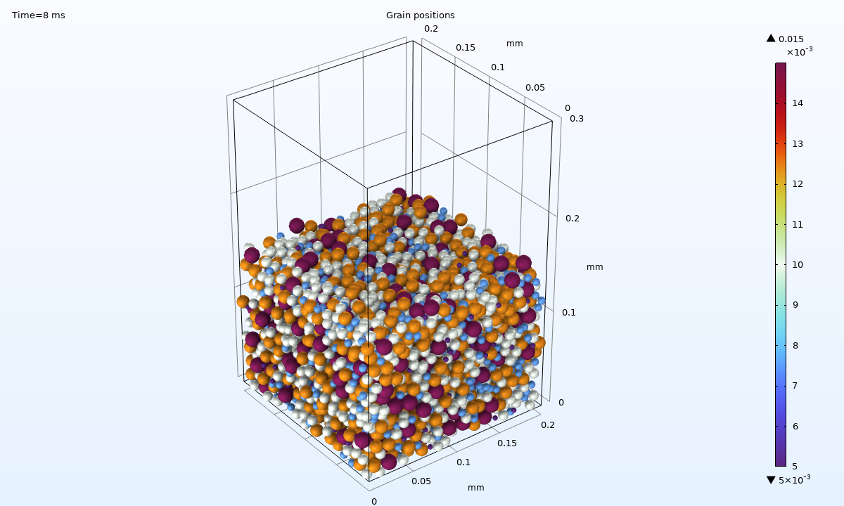
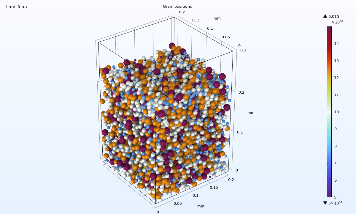
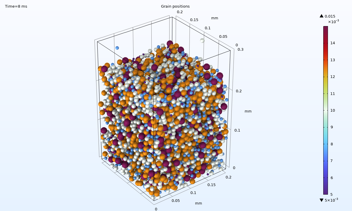
Left: the packed grains, using the Hertz–MD model. Middle: the packed grains, using the Hertz–MD with adhesion model. right: the packed grains, using the Hertz–MD with adhesion model with van der Waals forces enabled.
Including adhesion lowers the final packing fraction in this example, while adding van der Waals forces produces a smaller, additional decrease.
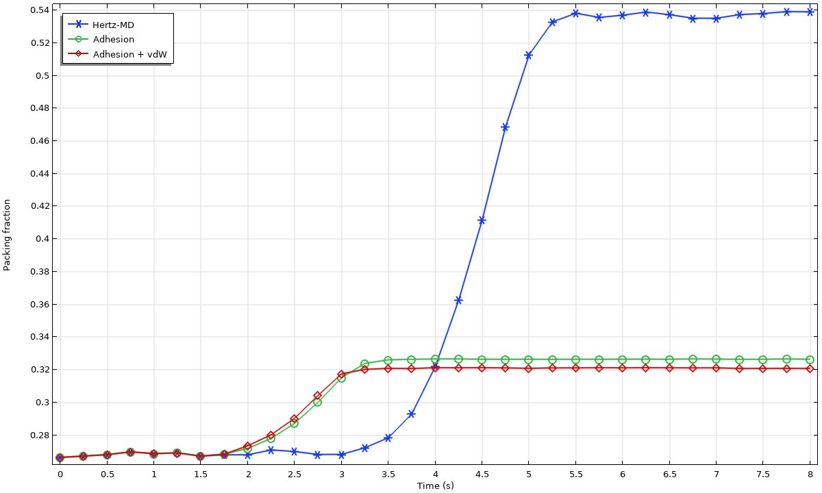
In this example, the Hertz–MD model predicts a significantly higher packing fraction than the models that include adhesive interactions. The Granular Flow Module can account for adhesive and van der Waals forces when these interactions significantly influence grain packing.
2. Hopper Flow
Hoppers that store and discharge granular materials are used in the agriculture, food processing, manufacturing, mining, and construction industries. The controlled material discharge from a typical funnel-shaped hopper often exhibits some combination of two flow patterns: mass flow and funnel flow.
In mass flow, the entire granular bed moves when material is discharged. This pattern typically follows first-in, first-out behavior, with the lower layers discharging before the upper layers and limited mixing between them.
In funnel flow, grains move through a flow channel while surrounding regions remain comparatively stagnant. Material from different layers can mix during discharge, and some material may remain near the walls. Hoppers that exhibit this type of flow have the advantage of having a smaller footprint and thus may be preferred in applications where space is a constraint.
Left: mass flow. Right: funnel flow.
This example model considers how the shape of a hopper design influences the flow pattern and thus the results. Two hopper designs are modeled, with hopper walls inclined at 15° and 75° from the vertical. For each design, a total of 150 grains with equal diameters of 10 mm are released at the inlet boundary every 20 ms up to 0.58 s, leading to a total of 4500 grains. The grains are allowed to settle under gravity for the first 1.0 s, after which the outlet is opened to allow the discharge of the stored material for a total of 4.0 s.
The time-dependent simulations show mass flow for the hopper with walls inclined at 15° from the vertical and funnel flow for the hopper with walls inclined at 75° from the vertical.
A Parametric Sweep study compares the two hopper designs, while coloring grains by release time helps visualize the discharge sequence and mixing between layers. The Bounding Box feature removes grains that have left the region of interest to improve computational efficiency.
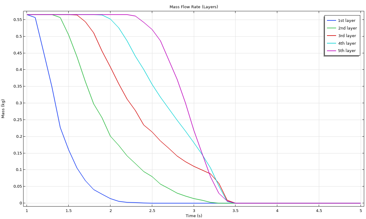 The mass remaining in each grain layer for the hopper with walls inclined at 15° from the vertical.
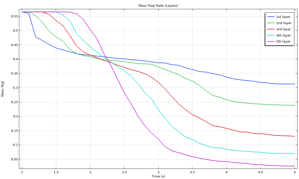 The corresponding results for the hopper with walls inclined at 75° from the vertical.
3. Angle of Repose
The angle of repose is the angle between the surface of a stable granular heap and the horizontal plane. This angle often depends on a variety of factors, including the size and shape of the particles, surface roughness, friction coefficients, and density. The angle of repose is therefore a complex property of the granular system, and it is often used in material characterization.
This model uses a similar hopper geometry as in the Hopper Flow model. Here, a total of 5000 grains, 20 mm in diameter, are deposited through the hopper outlet and onto the surface below. Once the grain heap stabilizes, the grain positions are used to compute the angle of repose. The grains are colored by speed in m/s, with their very low speeds indicating that the heap has stabilized.
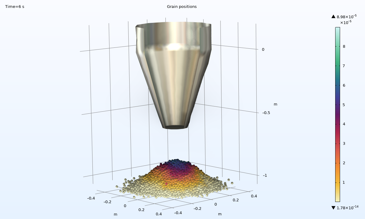 The heap of grains formed after emptying the hopper.
The outline of the left and right sections of the free surface, along with their least-squares fit, are shown in the figures below. The least-squares fit obtained for each section shows that the heap’s outline is fairly linear.
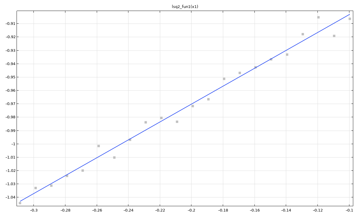
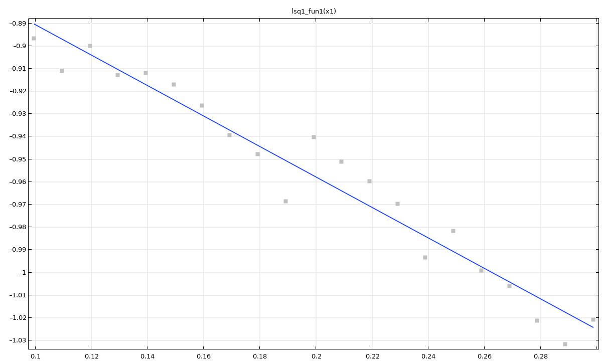
Left: the outline and linear fit for the left section of the heap. Right: the outline and linear fit for the right section of the heap.
4. Mixing Grains in a Rotating Drum
Many industrial applications necessitate uniform mixing of different granular materials. To achieve this result, organizations commonly employ rotating drums that include baffles to disrupt bulk flow. In this model example, we will look at how the number of baffles in a rotating drum influences the flow of materials.
The model uses the Granular Flow interface to simulate the mixing of two different grain types within a rotating drum. The extent of mixing is quantified using four mixing indices — Kramer, Lacey, Beaudry, and Valentin — calculated from the grain positions using a model method.
The mixing process with four baffles.
Mixing process with eight baffles.
The evolution of the four mixing indices provides a quantitative comparison of the two drum designs.
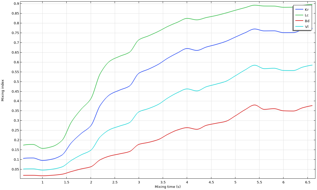 Evolution of the mixing indices with four baffles.
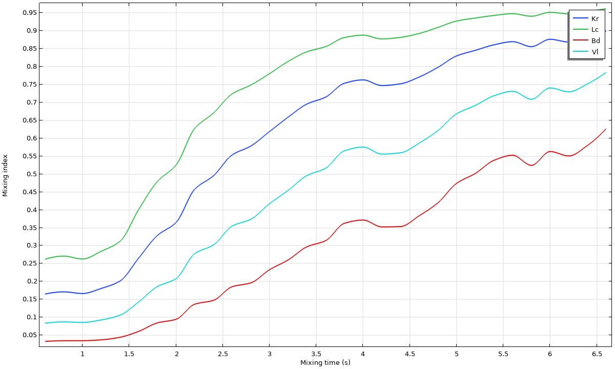 Evolution of the mixing indices with eight baffles.
For the conditions studied, the drum with eight baffles produces faster mixing and higher final mixing-index values than the drum with four baffles. These results can help teams assess drum designs before manufacturing.
5. Thermal Conduction in Granular Materials
Granular materials are a common insulator in industrial systems. The arrangement of grains influences heat transfer paths, making the insular properties of the granular mass dependent on their packing density and orientation.
Here, we will look at an example study involving a two-stage DEM simulation of thermal conduction in compressed granular materials. In the first stage, a top wall moves downward under an applied pressure of 20 kPa, compressing an assembly of spherical grains. The resulting grain arrangement provides the starting point for the second stage, which examines heat transfer through the bed. This process reflects manufacturing applications in which compaction is used to increase packing density and modify a material’s mechanical and thermal properties.
Grains undergoing compression.
In the second stage, the compacted granular bed is subjected to thermal conduction with a fixed temperature boundary condition of 300 K set for the bottom wall. Grain motion is frozen during this stage, assuming that the compacted bed remains mechanically stable. Only conductive heat transfer through grain–grain and grain–wall contacts is considered.
Solving the thermal stage separately allows larger time steps than those needed to resolve grain contact dynamics, reducing computational cost. In this example, 8 hours of thermal evolution are simulated in approximately 30 seconds of computation time.
Thermal conduction in the granular material over eight hours.
6. Power Spreading Using a Moving Roller
Additive manufacturing techniques such as powder bed fusion (PBF) rely on obtaining thin uniform layers of powdered materials. The quality of the powder bed depends on its packing density, uniformity, and thickness. These properties are influenced by the roller geometry and motion. This process involves heaping the powder in front of the bed and employing the moving roller to flatten the powder evenly over the area. Different roller speeds and geometries can be used to achieve different qualities in the bed.
In this model example, 20,000 grains (all 1 mm in size) are released onto the bed and allowed to settle. Then, the roller is set in motion with a translational speed of 100 mm/s for a total linear traversal length of 163 mm. The roller also rotates with an angular speed of 6 rad/s around its axis, resulting in the formation of a compact powder bed. The roller’s combined translational and rotational motion is prescribed using the Wall Movement settings. Sequential studies simulate grain settling, heap formation, and spreading.
The moving roller flattening the grain heap into a uniform powder bed.
The resulting bed is analyzed using packing fraction, grain-height distribution, and coordination number — the number of contacts each grain has with other grains. The packing fraction remains approximately constant at 0.47 along the bed, indicating relatively uniform packing.
7. Screw Conveyor
Screw conveyors can transport bulk granular materials horizontally or over an incline while also incorporating other specialized tasks, such as heating, cooling, and drying. These conveyors are widely used in food processing, pharmaceuticals, chemical industries, agriculture, cosmetics, and plastics, among other areas.
In this example, we’ll look at a screw conveyor model that highlights how the Granular Flow Module can be used to study the behavior of grains depending on how they are released into a screw conveyor. Moreover, this model highlights how the module can be used to build complex geometries for granular flow applications.
The screw conveyor transporting grain.
In this example, the grains have a density of 4200 kg/m3 and a diameter of 10 mm. They are released in 10 batches of 2500 grains, in intervals of 0.5 seconds. The screw is rotated at a constant angular speed of 120 rpm, and the simulation lasts 20 seconds. The screw rotation is prescribed using the Wall Movement settings, and a Force Accumulator subnode evaluates the forces exerted by grains on the screw. A model method calculates the mass flow rate through a plane within the conveyor.
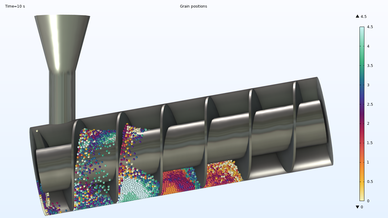
Grain positions at the end of 10 seconds.
The image shows grain positions at 10 seconds, colored by release time. Most grains from each batch remain clustered, although partial mixing occurs during transport. Some grains remain near the inlet because of the conveyor’s inclination and the clearance between the screw blade and casing. The throughput and screw-load results can support comparisons of rotational speed, conveyor inclination, and screw geometry.
Next Steps
Learn more about the Granular Flow Module and how it can be used to simulate the behavior of granular materials:
Explore the Tutorial Models
Ready to explore the models featured in this blog post? Find them in the Application Gallery, along with many other models for simulating granular flow:



Comments (0)