Magnetic resonance imaging (MRI) systems must produce high-resolution images in order for doctors to accurately diagnose their patients. To achieve this level of image quality, there must be a known reliable base magnetic field distribution within the MRI machine and its components, such as birdcage coils. This is where simulation comes in. By designing MRI birdcage coils with the COMSOL Multiphysics® software, you can manipulate and optimize the magnetic field and improve the scanned data that MRI machines generate.
A Brief Introduction to MRI Systems
Magnetic resonance imaging is noninvasive technology that generates detailed images of structures inside the body. Such images are widely used in the medical and biomedical fields to help doctors detect, diagnose, and monitor diseases and other health issues.
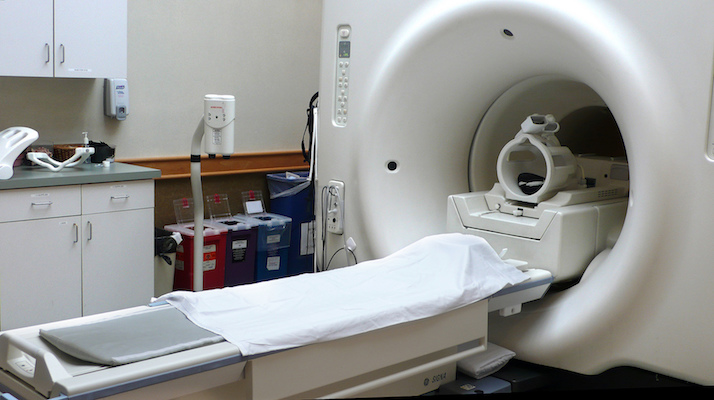
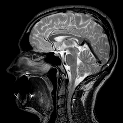
An MRI machine (top) and an MRI-generated image of a head (bottom). Top image by liz west — Own work. Licensed under CC BY 2.0, via Flickr Creative Commons. Bottom image by Mikael Voss — Own work. Licensed under CC BY-SA 4.0, via Wikimedia Commons.
In short, MRI machines work by subjecting a patient inside a small confined space to a strong magnetic field that alters the alignment of the protons in their body. The MRI machine also produces a current that affects the protons’ spins. After the RF field is turned off, the protons return to an equilibrium state, releasing energy. A receiving coil, such as the birdcage coil, detects this change, which is later turned into an image.
Images produced by MRI machines give doctors a view inside the human body, enabling them to accurately diagnose their patients. However, if the magnetic field distribution within a birdcage coil fluctuates due to its design, the image quality can be poor — negatively affecting the doctor’s ability to diagnose their patient. To help doctors avoid this issue, engineers can optimize MRI birdcage coil designs with simulation.
Designing and Optimizing an MRI Birdcage Coil in COMSOL Multiphysics®
The example model that we discuss today demonstrates how to design a birdcage coil and optimize its magnetic field around a phantom human head to create the desired distribution. It also examines the circular polarity of the magnetic flux density (B-field) around the phantom and surrounding air.
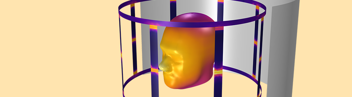
The magnetic flux density surrounding a human head phantom and air within a birdcage coil.
At the center of our geometry is a human head phantom that is contained within a birdcage coil. The coil (colored orange in the following image) includes lumped ports and capacitors, which we define using lumped elements. The lumped ports provide quadrature excitation for the coil, while the capacitors determine the coil’s resonance frequency and generated field’s homogeneity. We obtain the homogeneous magnetic field along the circular perimeter through a combination of quadrature excitation and an appropriate amount of lumped elements within the coil.
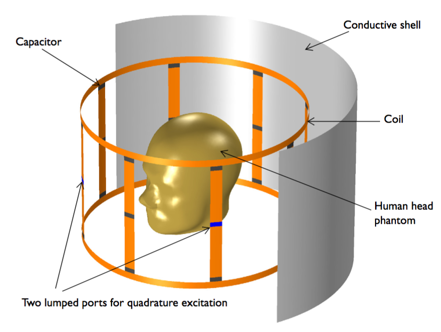
The birdcage coil model geometry. The conductive shell’s front is removed to help visualize the model. The image does not show the absorbing boundaries.
Surrounding the coil is an RF shield, which is assigned a perfect electric conductor (PEC) condition, just like the coil surfaces. The air domain around the coil is represented by an air sphere, with scattering boundary conditions at the sphere’s boundaries to prevent reflections into the modeling domain. As for the mesh, we use the Automatic mesh control option in the Electromagnetic Waves, Frequency Domain interface.
In this model, we can find the optimal magnetic field for the surrounding air at a desired Larmor frequency by performing a parametric sweep for the capacitance of the coil’s lumped elements. We quantify the magnetic field’s homogeneity by determining the electric field’s standard deviation around the phantom. As for the circularity, we estimate the axial ratio of the magnetic field around the phantom.
Analyzing the Field Distribution and Circularity Within an MRI Birdcage Coil
Let’s compare the magnetic field results that don’t include the human head phantom with those that do. For our study without the human head phantom, we are able to determine an optimal value for the lumped elements’ capacitance at the Larmor frequency. Further, we can assume that the flux is rotating circularly, since the magnetic flux density’s real part is nearly orthogonal to its imaginary part.
When the coil is loaded with a human head phantom, the results show that the high dielectric loading in the center of the coil causes the field’s uniformity and circularity to become distorted. In this case, we could tune the coil’s capacitors to address this issue.


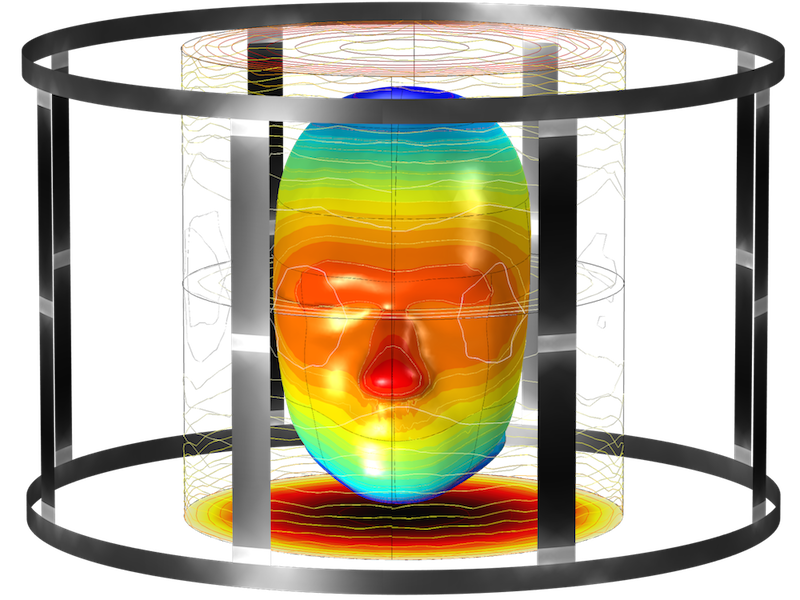
The magnetic density norm distribution around the air phantom and coil (left) as well as around the coil and human head phantom (right). The arrow plot represents both the real (red) and imaginary (blue) parts of magnetic flux density.
Moving on, let’s examine our results for the integration of the magnetic flux density’s axial ratio as well as the standard deviation of the electric field norm around the human head phantom. By comparing different values of the lumped elements’ capacitances, we see that the optimal capacitance value for achieving a circularly polarized magnetic field is around 28.5 pF. Results like these show that COMSOL Multiphysics can be used to help design and optimize MRI birdcage coils.


The integration of the magnetic flux density’s axial ratio (left) and standard deviation of the electric field norm (right) around the model that includes the human head phantom.
Additional Reading
- Browse these blog posts to learn more about modeling medical devices:


Comments (0)