

Modifying imported meshes can be helpful in certain scenarios, like when you need to move or rotate the mesh, when it has holes or self-intersections, or when you want to intersect it with a plane. In this blog post, I will discuss the functionality for editing and repairing surface meshes that’s available in the COMSOL Multiphysics® software. I will demonstrate various operations and workflows for handling imported meshes and point to existing tutorial models and other relevant resources for learning more. This post is the first of a two-part series; the second post demonstrates the process of combining imported STL mesh with an imported CAD assembly.
Table of Contents
- Formats for Importing Surface Meshes
- Repairing and Editing Imported Surface Meshes
- Demonstrating with a Skull Mesh:
- Moving and Rotating Imported Meshes
- Repairing Holes and Problems Like Intersecting Elements
- Making a Cutout of the Mesh
- Removing Elements from Meshes
- Remeshing Faces to Control the Element Size
- Merging Meshes, Uniting Meshes, and Creating Computational Domains
- Joining Domains and Creating Selections
- Concluding Thoughts
Formats for Importing Surface Meshes
The 3D surface meshes I’ll focus on in this blog post often originate from 3D imaging. In a medical application, for example, a 3D surface mesh can be used to describe the geometry of an internal organ or even the whole body. Common file formats supported for import into COMSOL Multiphysics® are STL, 3MF, and PLY. STL is perhaps the most widely recognized format since it is also used for 3D printing, so I’ll use it for discussion here. However, note that the mesh editing methods I’ll present in this post will work for any mesh file in a supported format imported into a Mesh-Based Geometry sequence.
STL files do not contain any boundary or domain information, so this will need to be created either during import, which is done automatically, or manually after import. Boundaries are always created during import. However, domains — i.e., volume regions you can assign materials to and fill with a volumetric mesh — cannot be created during import if the imported mesh has intersecting elements due to overlapping regions (which you’ll see an example of shortly). Most physics interfaces in the software require domains, so it is important to create them. For meshes with overlapping regions, you need to first resolve the intersections so that there are edges tracing all of them. Then, you can manually create the domains. Filling the domains with a volume mesh is done when the computational mesh is generated, which I demonstrate in Part 2 of this series.
Note: For designs created in CAD software, it is recommended to export them in any of the formats supported for import with the CAD Import Module.
Repairing and Editing Imported Surface Meshes
In addition to the challenges of working with the STL format, another common challenge that arises when importing a surface mesh is that the quality of the triangular mesh is often too poor to be readily used for finite element simulation. From a simulation perspective, the quality of a mesh is poor if it contains:
- Holes or self-intersecting boundaries preventing domain creation
- Thin spikes or other unwanted irregularities in shape
- Triangles with very acute or obtuse angles
- Triangles that differ greatly in size
COMSOL Multiphysics® supports a range of operations for handling all of these challenges, as well as for making other sorts of common mesh edits. You can use these capabilities to:
- Move, scale, and rotate the imported mesh
- Modify the repair tolerance during import
- Fill small or large holes in the mesh
- Remove elements from the mesh, replacing them with new meshed surfaces
- Combine and merge meshes
- Combine imported mesh with parametric CAD designs (or geometry drawn in COMSOL Multiphysics®) to run parametric sweeps
- Intersect multiple imported meshes with each other or with a plane
- Remesh the surfaces to control element size and the shape
- Use a curved surface representation of nonplanar boundaries
 Editing done to the surface mesh of a skull.
In this blog post, I’ll use a mesh of a human skull to demonstrate the workflows for several of these actions.
Demonstrating with a Skull Mesh
The mesh for the following demonstrations was obtained from the NIH website. (Ref. 1) Here, I’ve imported the mesh into a Mesh-Based Geometry sequence, which is a sequence that defines the geometric model with the domains and boundaries needed to set up and solve any physics. Alternatively, you can do the import, repair, and editing in a Mesh Part sequence, as is demonstrated in Part 2 of this blog series and in the STL Import Tutorial Series. Moving portions of the work to one or several mesh parts is good for organizing it but also for when you want to reuse the same mesh in several sequences or use mesh parts as construction geometry (also shown in Part 2).
For this example application, I’ll need to rotate and move the mesh to get it into position, remove some elements that are not needed, and calculate the intersection between the meshes of the bone and teeth. I will also touch on some other useful operations and workflows that can help in other cases. To aid with visualization, the mesh surfaces are colored as in the image above, unless stated otherwise. In the example model that can be downloaded at the end of this post, the boundaries remain gray until the colored selections are created at the end.
Moving and Rotating Imported Meshes
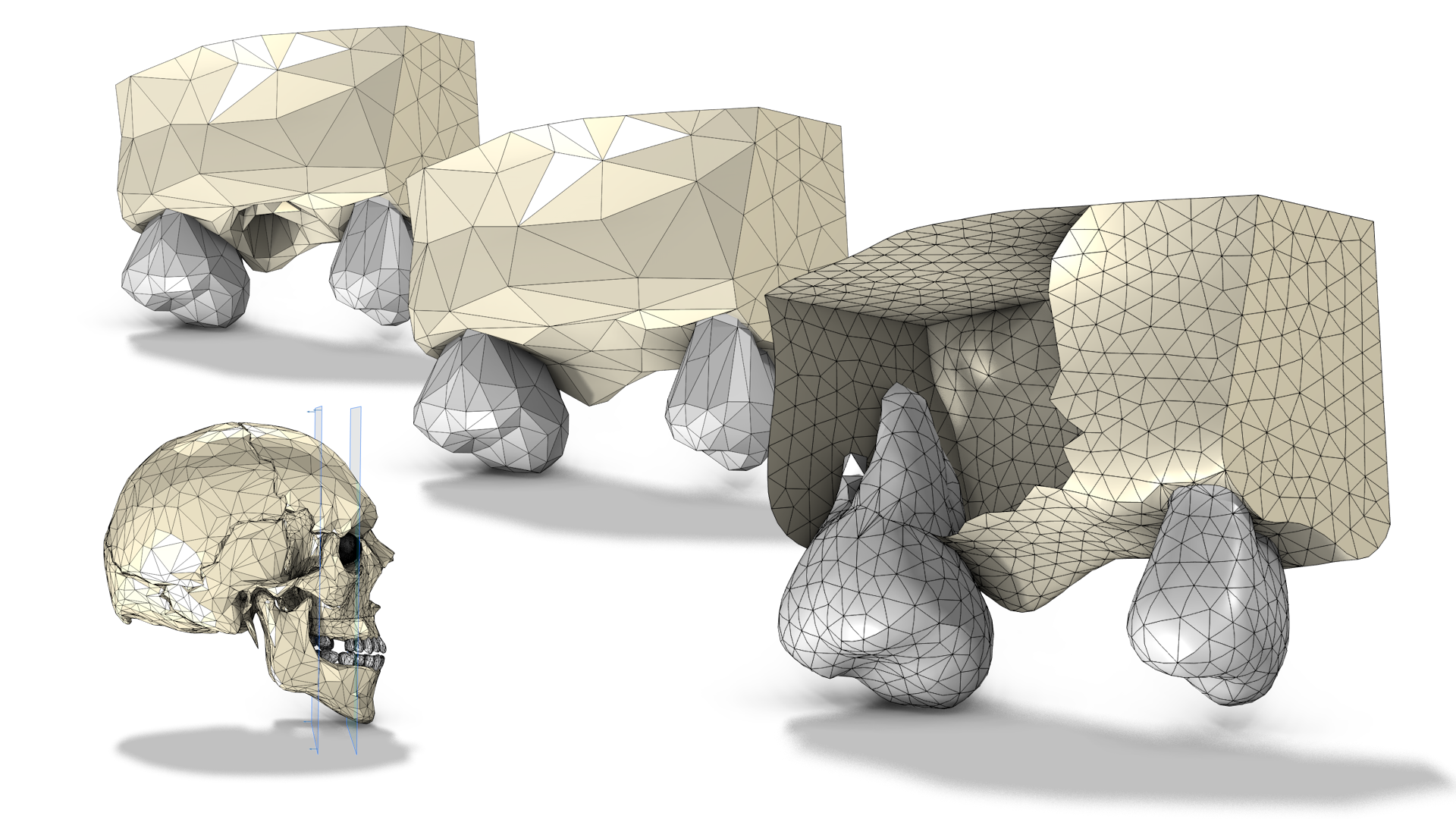
Many 3D imaging techniques are performed on the bodies of humans who are lying down, which means that an imported mesh may need to be rotated to, for example, put a body model in an upright position. Moving and rotating an imported mesh is done by adding one or several Transform attributes to the Import node. Rotation around multiple axes requires several Transform attributes.
For this example, I implemented a rotation by first aligning the z-axis to the axis specified by the Axis type setting; then, the mesh was rotated 83 degrees around the specified x-axis, and I added a displacement to place the mesh at the origin.
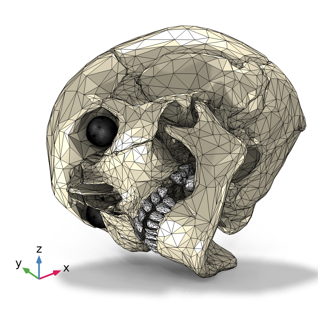
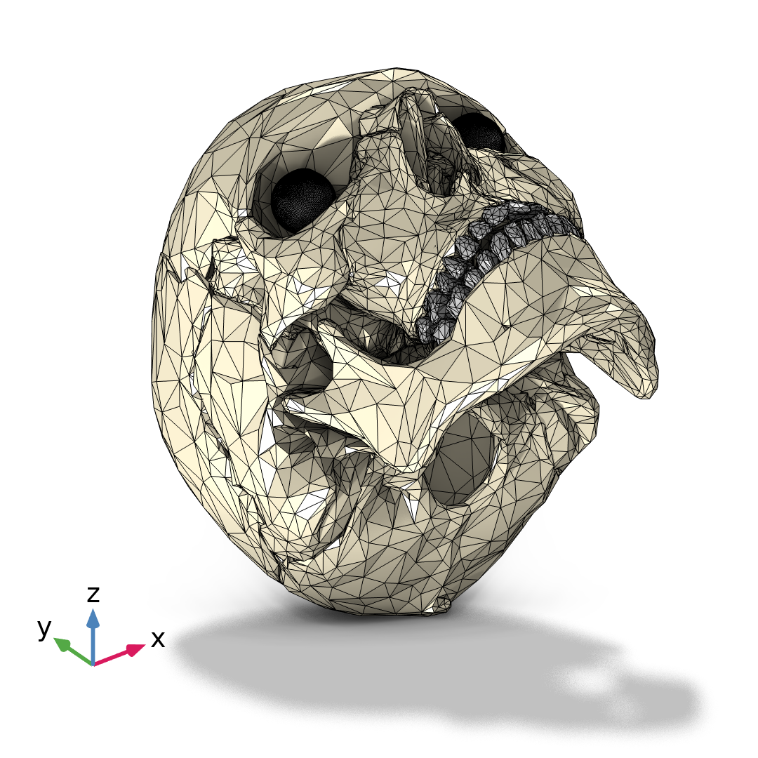
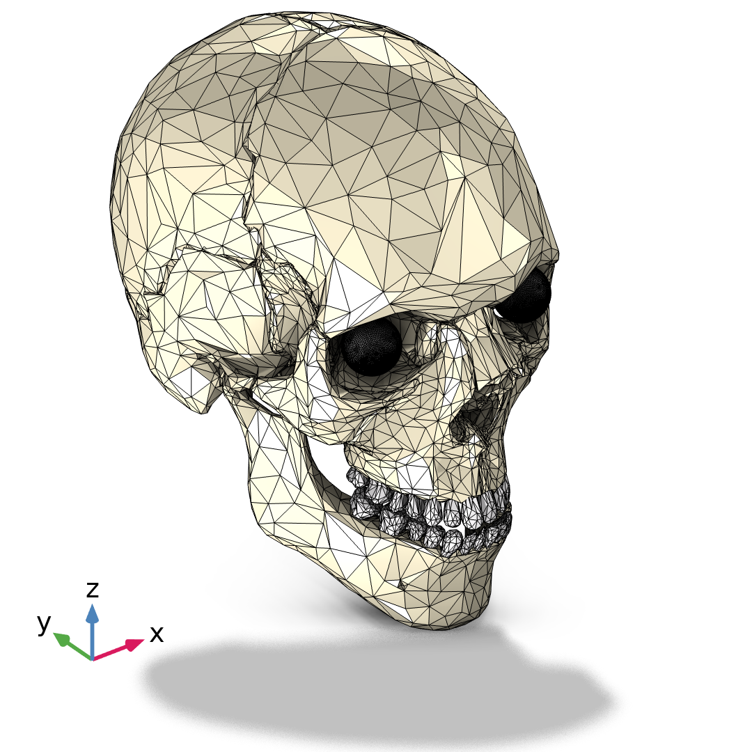
The orientation of the mesh in the file (left). By setting the Axis type to x-axis, the mesh is rotated to align the z-axis with the x-axis (middle). Lastly, the rotation angle of 83 degrees around the x-axis is applied (right).
Note that it is recommended to add any Transform attributes before doing any other editing or repair, as reimporting the mesh with new Transform settings will likely result in lost input selections in downstream features in the sequence.
Repairing Holes and Problems Like Intersecting Elements
During import or when building other operations, Information nodes may appear to notify you that there are holes in the mesh and provide you with a selection of edges that you can zoom in on.
To repair smaller holes relative to the overall size of the mesh (typically the size of one or a couple of mesh elements), it is often sufficient to increase the Repair tolerance of the import, as this can collapse elements or align a mismatch in vertex coordinates. For larger holes, or if increasing the repair tolerance doesn’t seal off all holes, try using the Fill Holes operation. If doing so fills all of the holes and the surfaces thus form watertight regions, the Fill Holes operation will also create domains inside the regions.
For problems like intersecting elements, as seen below at right, isolate the problematic region, delete the elements, and fill in the hole. For more details about this workflow, refer to the Removing Elements from Meshes section of this blog post.
The skull mesh at hand doesn’t require any repair of this kind, but the STL Import Tutorial Series includes several examples of smaller holes and intersecting elements, as can be seen in the following images. Download the application files to learn how to fix these.
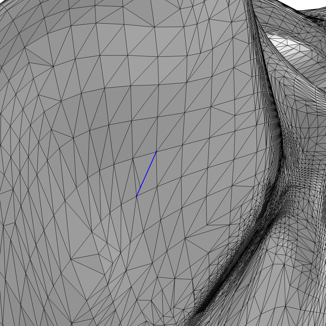
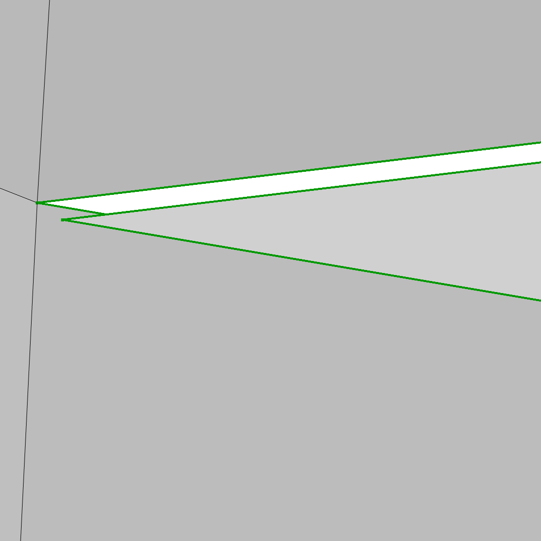
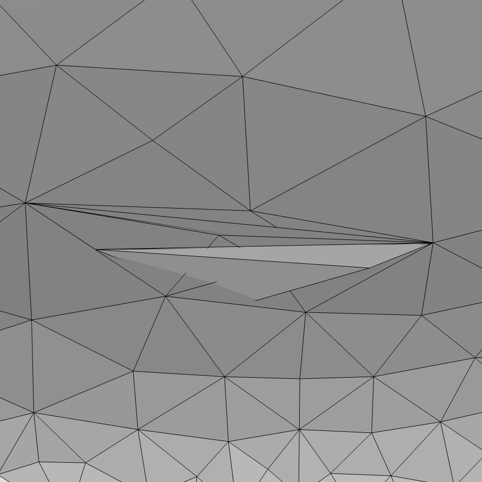
A hole with zero area (i.e., a slit) is bounded by edges highlighted in blue (left). A hole in the mesh caused by a mismatch in vertex coordinates (middle). Intersecting elements in an imported mesh (right).
Making a Cutout of the Mesh
What if you only want to include a smaller region of the imported mesh in the simulation? For example, with the skull mesh, I ultimately wanted to create a model to simulate a dental implant, so I didn’t need the full skull mesh. Assuming that parts of the mesh are not needed for the simulation, you can delete the parts of the mesh that you are not interested in. The skull mesh was imported as several mesh surfaces, which made it possible to extract the surfaces of the jaw bone and teeth using a Delete Entities operation, as shown in the following image.
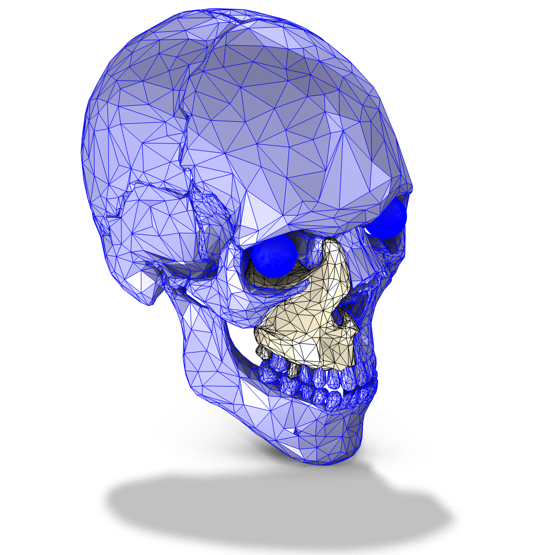 I used a Delete Entities operation to delete the parts of the mesh that I was not interested in; I only kept the upper jaw and two teeth (highlighted in light yellow).
Next, I used Intersect with Plane operations to cut the upper jaw bone into smaller pieces and then delete the parts that weren’t needed for the simulation. You can specify the planes using coordinate planes, points, coordinates, the normal vector, and more. Once a plane has been specified, one or several parallel planes can be added, as you can see in the bottom two of the following images. The Intersect with Plane operation is used to create selections of what is above and below the plane. You can use these selections to easily select what to delete.
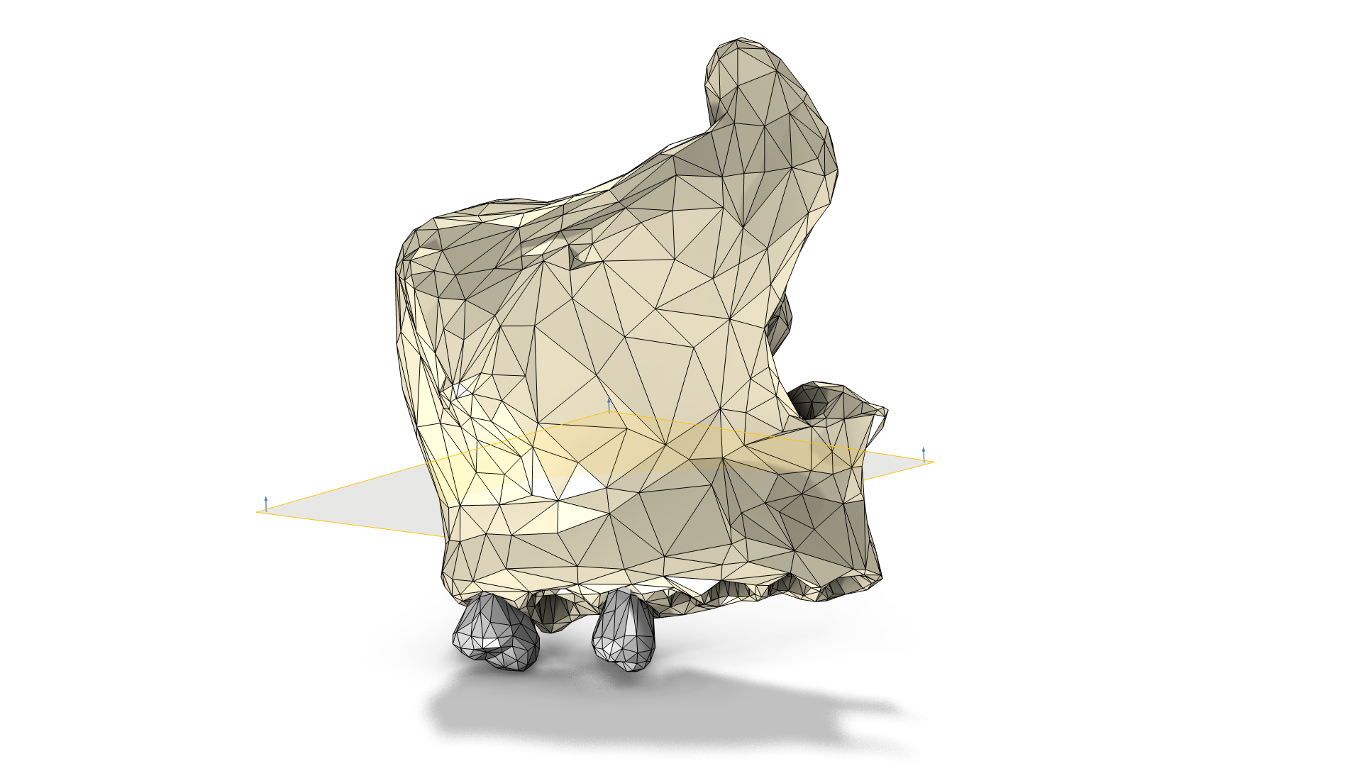
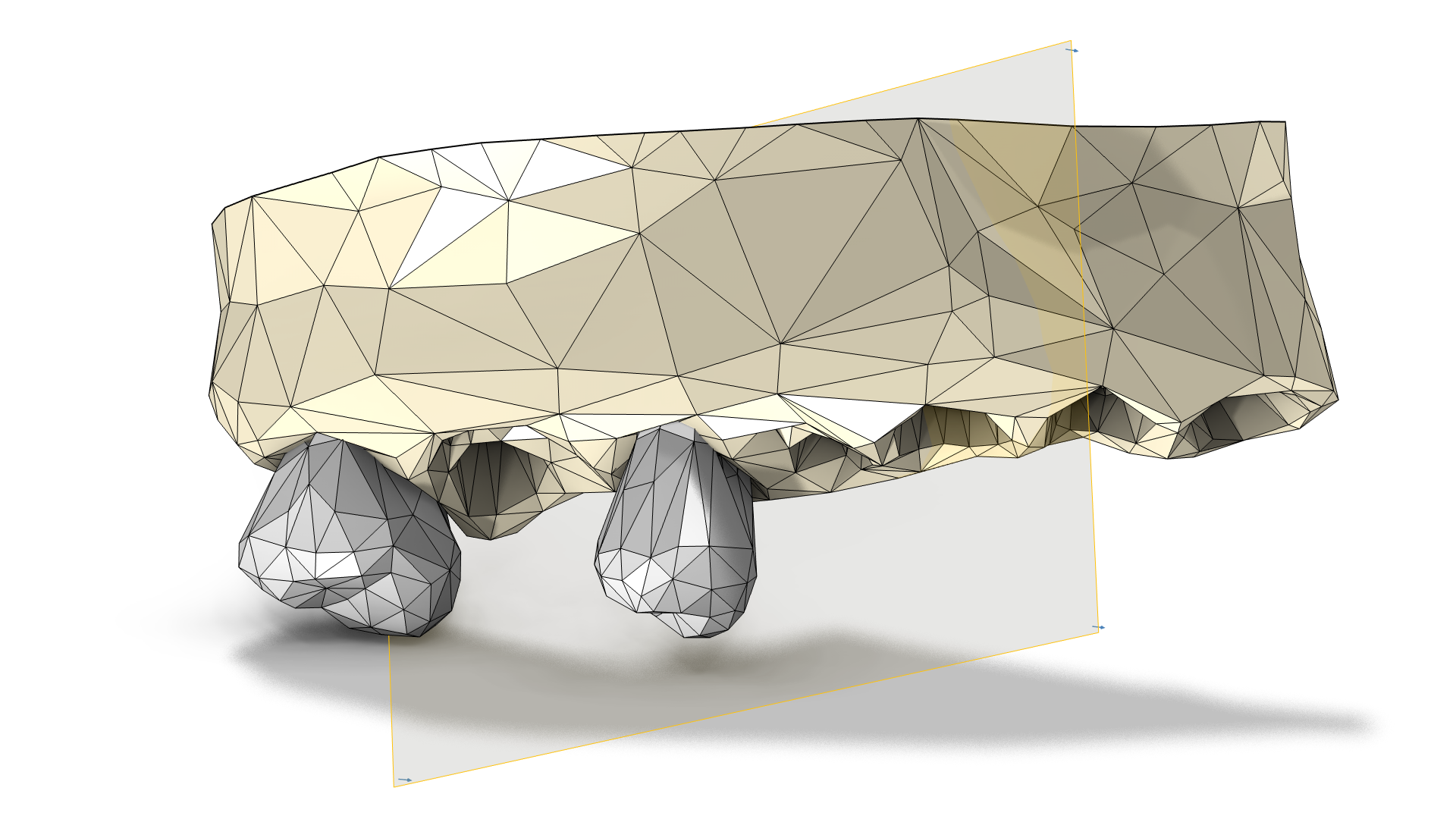
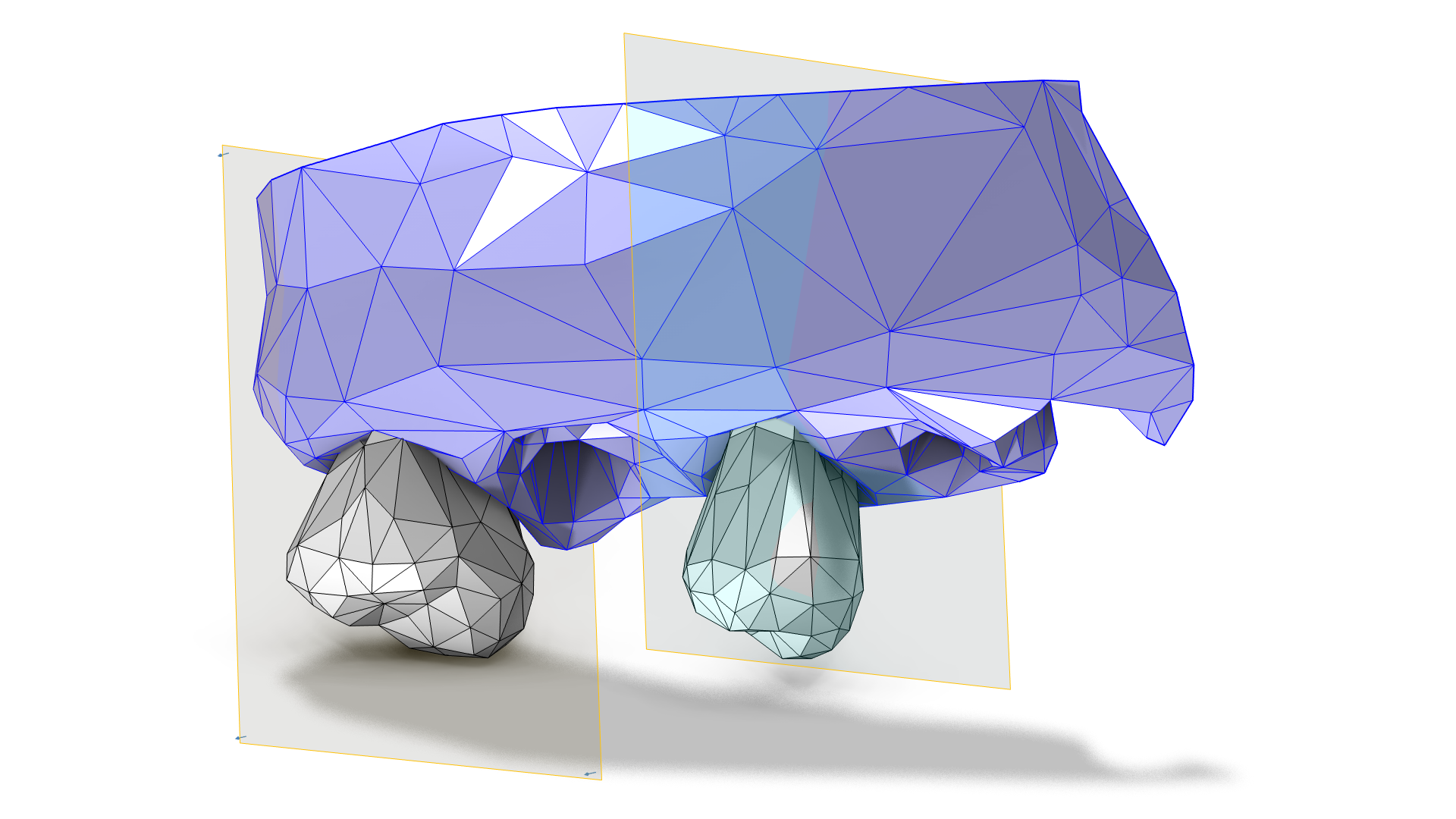
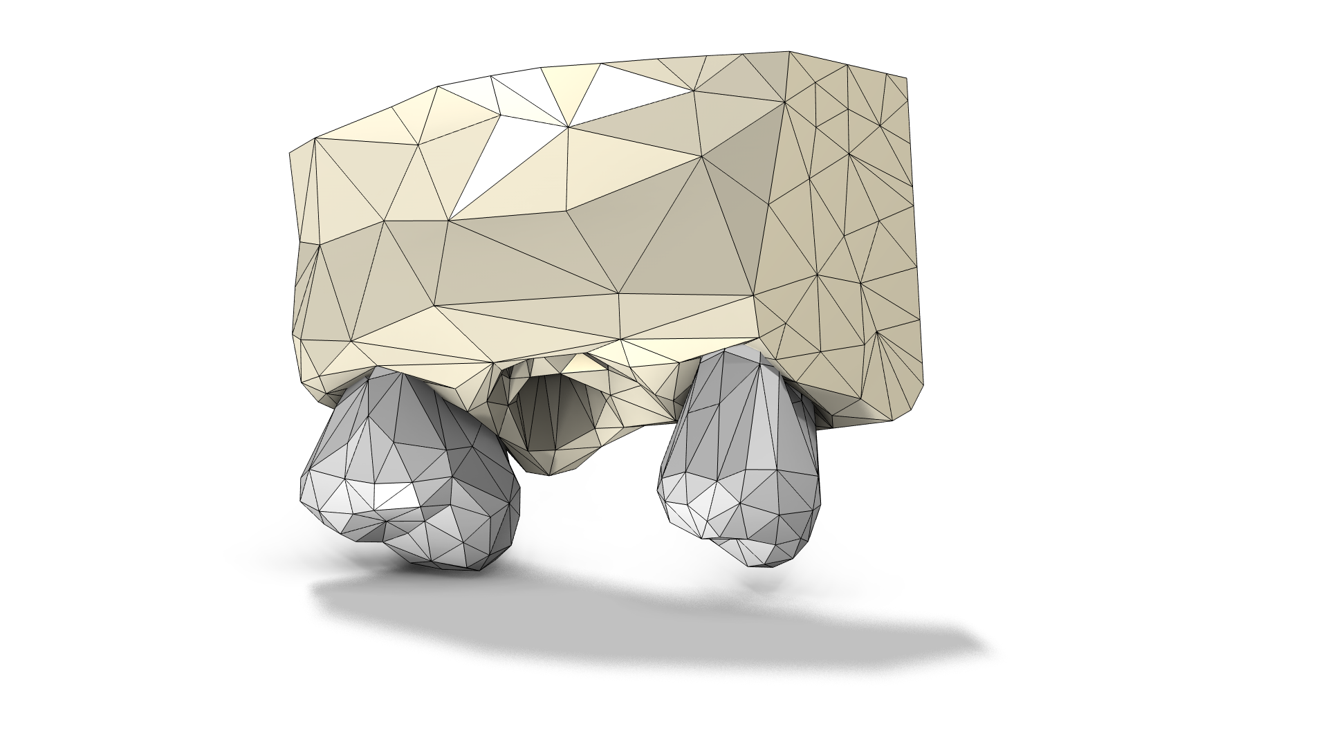
Clockwise from top left: I used multiple Intersect with Plane operations to cut the upper jaw into smaller pieces, deleting what was above and/or below the planes as I went.
Removing Elements from Meshes
For the skull mesh, I wanted to create domains inside the bone and teeth to assign materials to when adding physics to the model, and to do this I needed to resolve the intersection between the bone and teeth surfaces with a Union operation. As you can see in the following image, the surfaces intersect in a complex way, with small overlaps and gaps between the meshes. I also needed to resolve the intersection to remove the indents from the missing tooth because I wanted to simulate that the dental implant (to be added to the mesh in Part 2) had fully healed into the bone. It is easier to unite meshes where the intersection is reasonably close to 90 degrees rather than the small angles that the skull mesh had. Therefore, I removed a rather large portion of the bone surface and replaced it with a flatter new meshed surface.
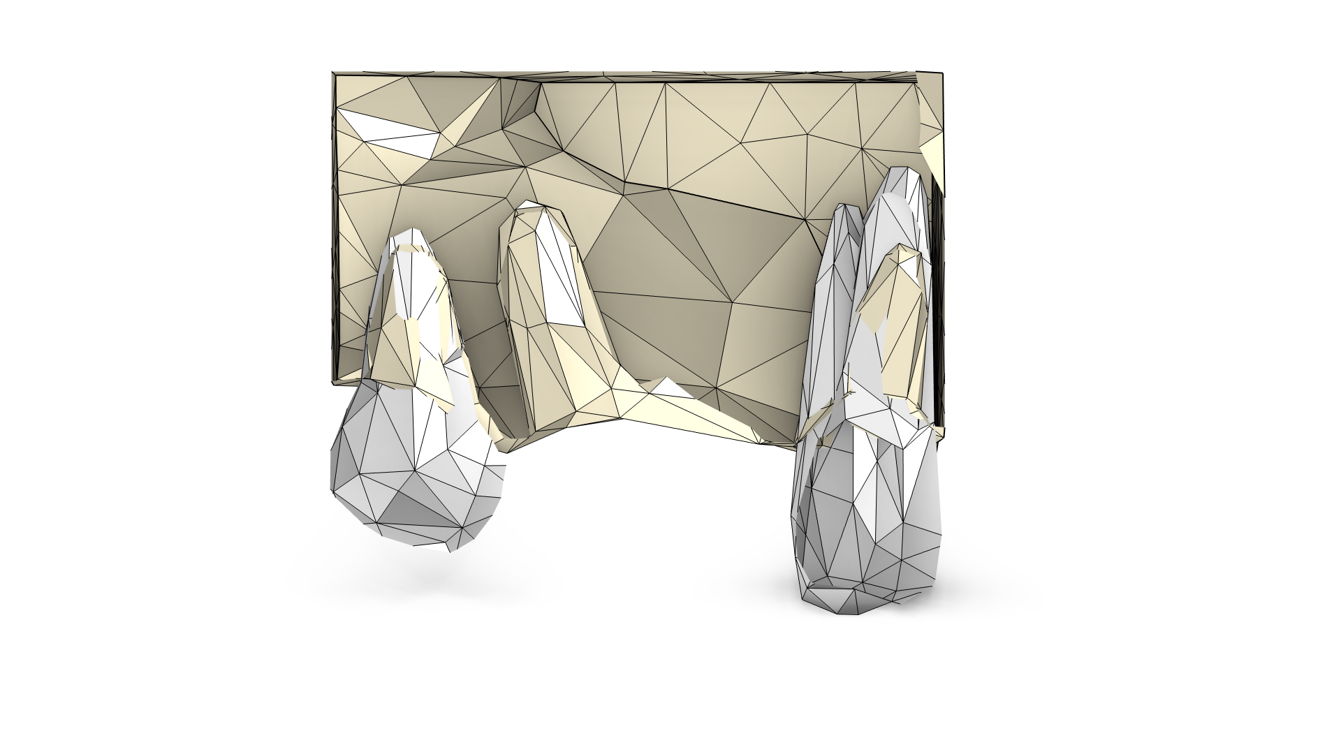 Using a Clip Plane operation to see inside the mesh. The surface of the bone (light yellow) contains depressions that intersect the teeth (white) and the future dental implant.
The workflow for removing elements typically consists of isolating the irregularity, deleting it, creating a new surface, and joining it with an adjacent boundary. Some STL meshes contain a large number of problematic regions, so isolating the surface can been automated by using the Mesh Partition with Ball add-in, which is available from the Developer tab in the software. The partitioning operations can quickly partition a mesh but are restricted to specific shapes or logical expressions by their respective settings. On the other hand, the Create Edges operation is more flexible, as you select each mesh edge manually. For practical reasons, the Create Edges operation is typically only used when isolating a smaller number of mesh elements.
I’ll demonstrate a workflow here that uses both types of operations and starts with loading the Mesh Partition with Ball add-in. To load the add-in into a model, click the Add-in Libraries button on the Developer tab. In the list of add-ins, select the checkbox for the Mesh Partition with Ball add-in, and click Done. Now, click the Add-ins button on the Developer tab and select Mesh Partition with Ball.
When the add-in is loaded into the model, middle-click with the mouse to place the center of rotation, which will be used as the center for the ball. Click the Create button in the Settings window for the add-in to add a Partition with Ball operation to the sequence with its center and radius filled in by the add-in. The settings can be changed if needed. In the example, I opted to only partition the largest bone boundary (colored blue at left in the following set of images), as that was the only boundary that contained elements I wanted to replace. For other use cases of the add-in, see the Spray Particle Deposition in Human Airways tutorial model.
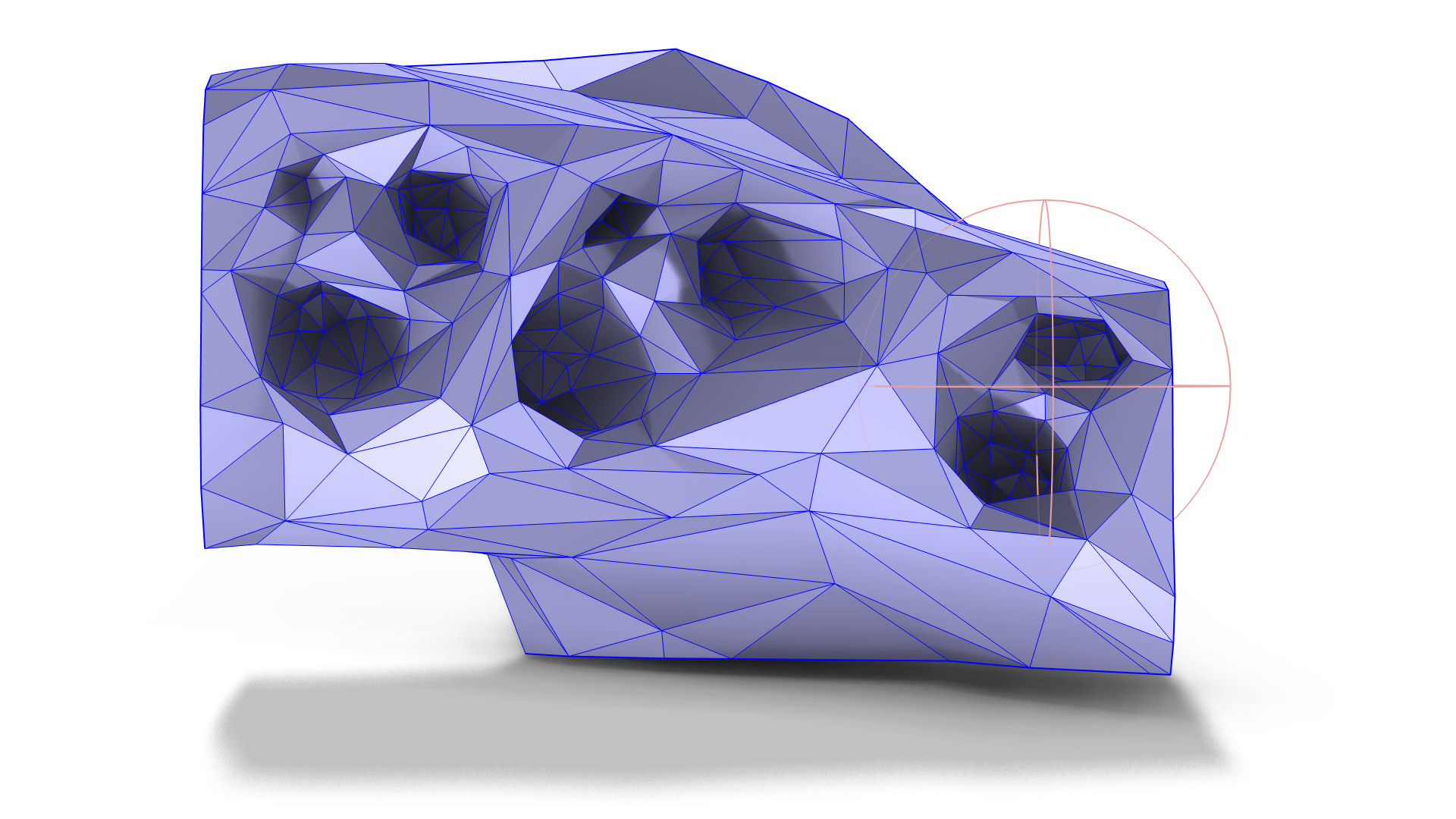
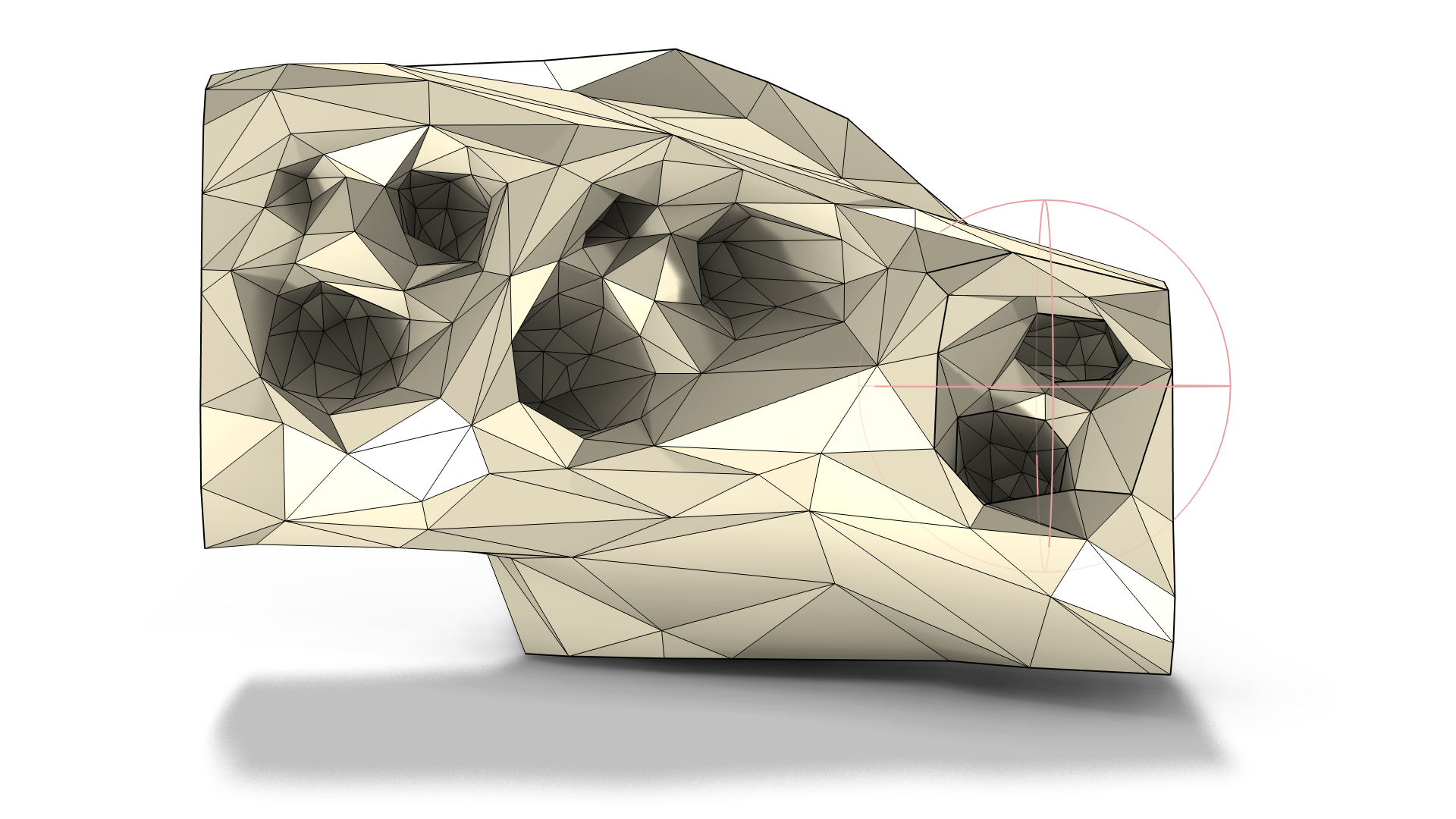
Looking at the mesh from below with the teeth hidden for visibility. In the Graphics window, middle-click the mesh to set the center of the ball. The radius of the ball (light pink) is set automatically by the add-in. The teeth are hidden for visibility (left). The resulting mesh after a Partition with Ball operation has been added to the sequence to isolate a region enclosed by the ball (right).
For the rest of the depressions I used the Create Edges operation, as the bone wall around the depressions in the middle was quite thin and clicking the edges manually gives you more control over which elements to isolate. With the Create Edges operation, you click the mesh edges in the Graphics window to create geometrical edges that will isolate a surface. These edges are selected to attach to the edges created by the add-in (the thicker black edges in the following image at left). Use of the Create Edges operation is also demonstrated in the STL Import Tutorial Series.
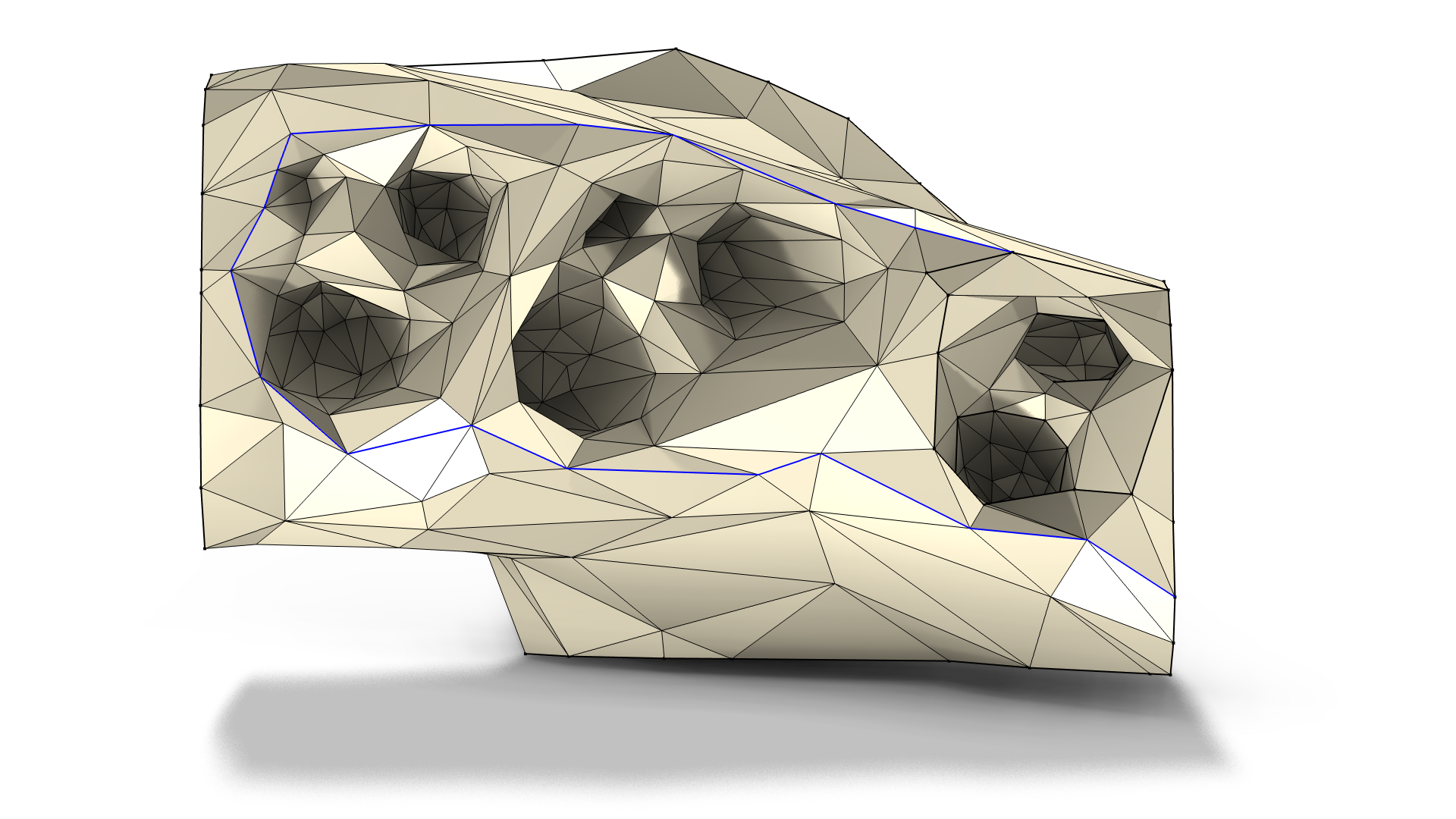
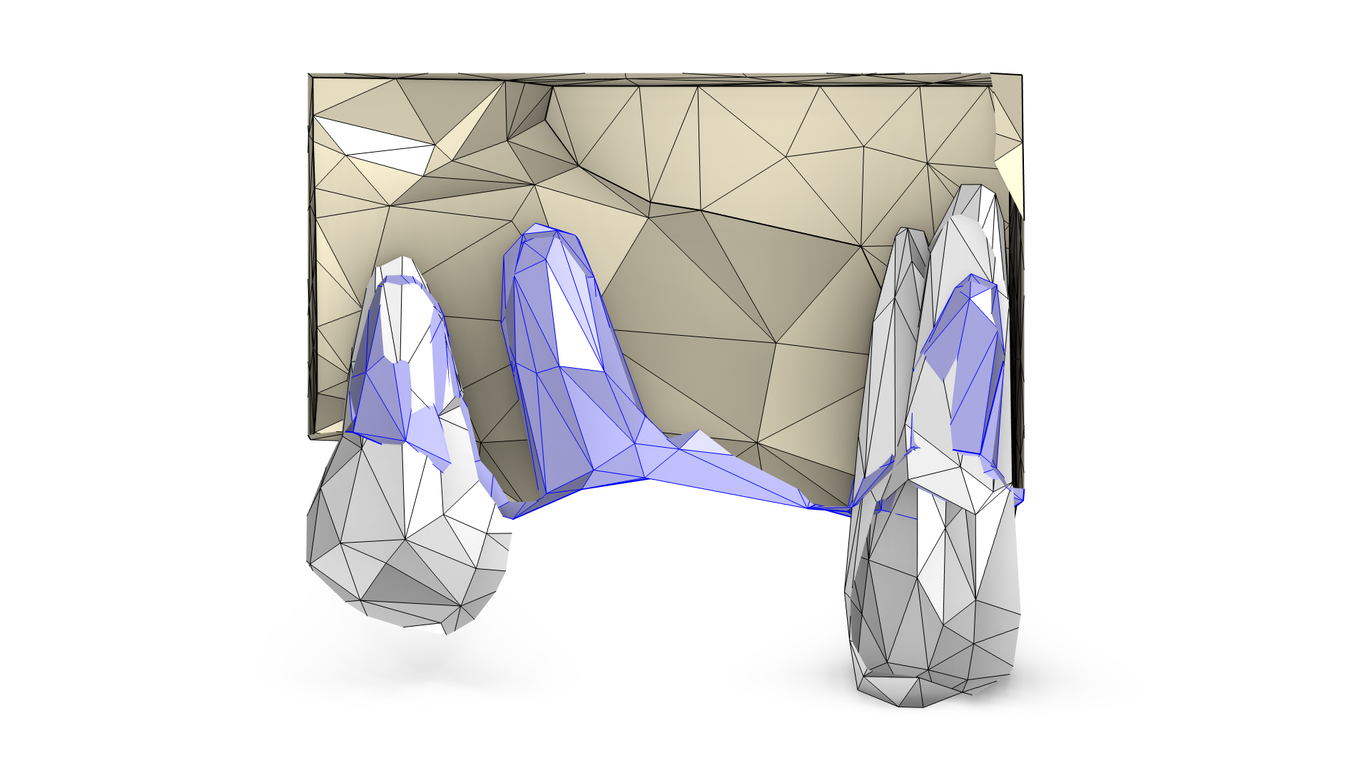
Click the mesh edges (highlighted in blue) in the Graphics window to form the bounding edges of the surface containing the rest of the depressions (left). Looking at the mesh from the side using a Clip Plane operation: The highlighted surfaces (blue) are selected to be deleted and replaced (right).
Once the depressions were isolated, I deleted the surfaces and created a new meshed surface using the Create Faces operation, as shown in the following images. The generated surface is a minimal surface, which means that it aims to be as planar as possible with a coarse mesh size. If the hole had been small compared to the bounding box of the mesh, I could have used the Fill Holes operation instead.
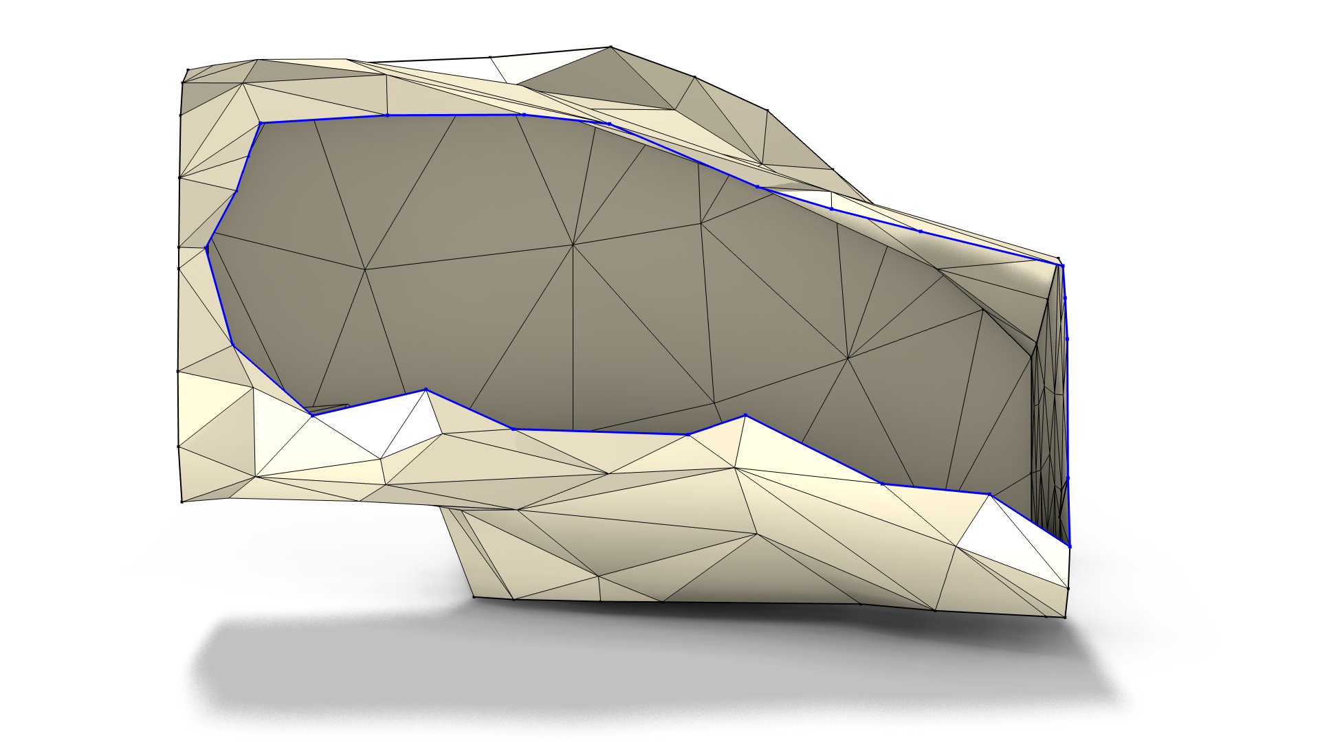
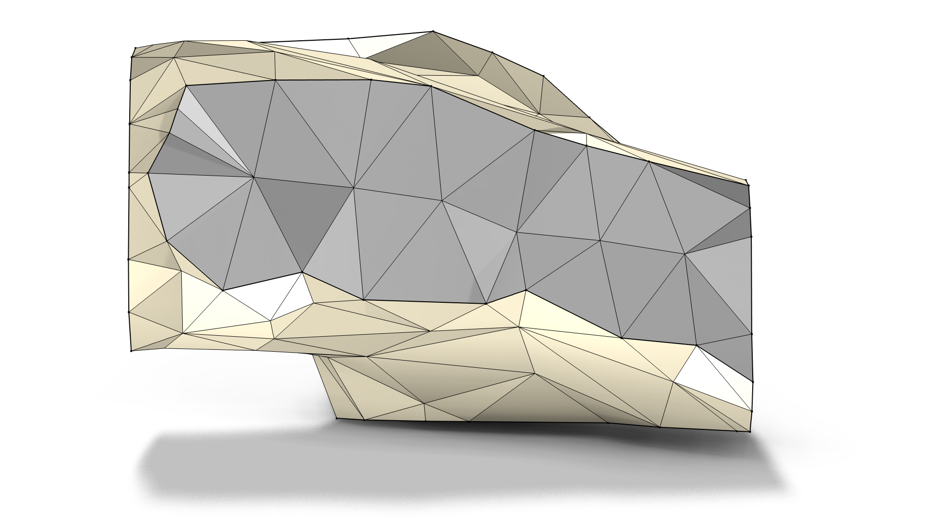
The highlighted edges (blue) are used as input to the Create Faces operation (left). In gray, the new meshed boundary (right).
Finally, I used the Join Entities operation to join the larger boundary of the bone with the newly created boundary.
Remeshing Faces to Control the Element Size
To help the Union operation calculate the intersections between the meshes of the teeth and bone, it’s ideal to have mesh elements of more equal size, as well as high-quality elements on the intersecting faces. Achieving these conditions can be accomplished by using the Remesh Faces operation. To gain more control over the element sizing, change the element size in the Size subnode. To get a similar size on all surfaces, regardless of the curvature and any narrow regions, set the Minimum element size and Maximum element size to similar or equal values. Note that the mesh generated when using the Remesh Faces operation is only to help the Union operation and to get a smoother representation of the surfaces. The Remesh Faces operation accomplishes the latter by placing new nodes on a curved representation of the surface derived from the linear mesh. The computational mesh is generated later in a Mesh sequence.
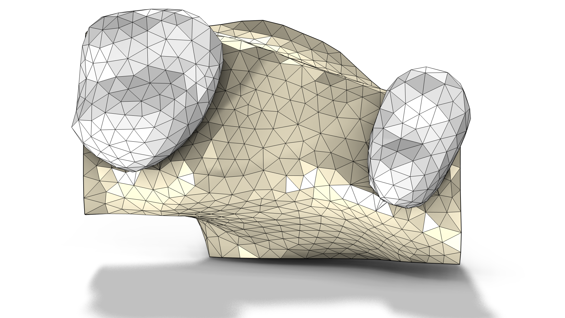 Remeshing the teeth and the joined surface of the bone to prepare them for the Union operation.
The Remesh Faces and Remesh Edges operations can also be used to control the shape of surfaces and edges. For an example where the Remesh Faces operation is used to smooth the mesh surfaces, see Generating a Simulation Mesh of a Femur From 3D Data.
Merging Meshes, Uniting Meshes, and Creating Computational Domains
Going back to the example of the dental implant, I used the Union operation to calculate the intersection between the overlapping meshes of the teeth and bone. The Union operation calculates the intersection edges, partitions the surfaces, and splits the mesh elements as necessary, as you can see in the following image at right.
If the Union operation reports problems with intersecting elements, keeping domains, or the like, try another mesh size in the Remesh Faces operation, try lowering the Absolute repair tolerance of the Union operation, and/or switch to the Linear option in the Placement of mesh vertices setting. When the Curved placement of vertices option is used (as shown in the middle image below), new mesh vertices are placed on a curved representation of the mesh surface that is derived from the linear mesh. The Linear option simplifies the problem, with the drawback of having more angular intersection edges.
For the example model, I used the Linear placement of mesh vertices option for the Union operation, which created edges tracing the intersections which the mesh conformed over (image at right).
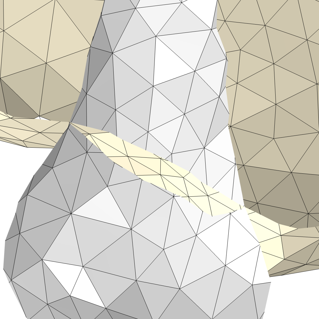
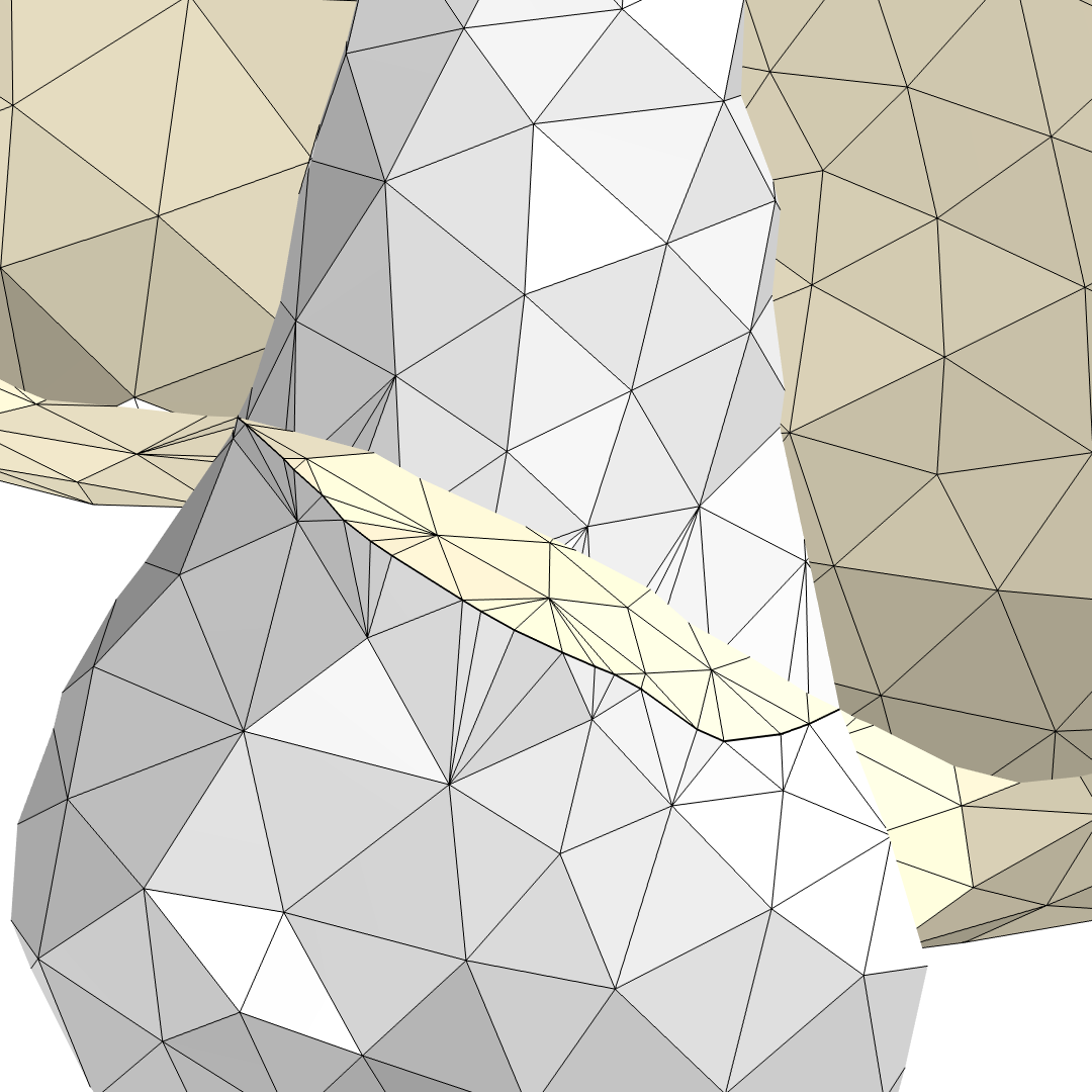
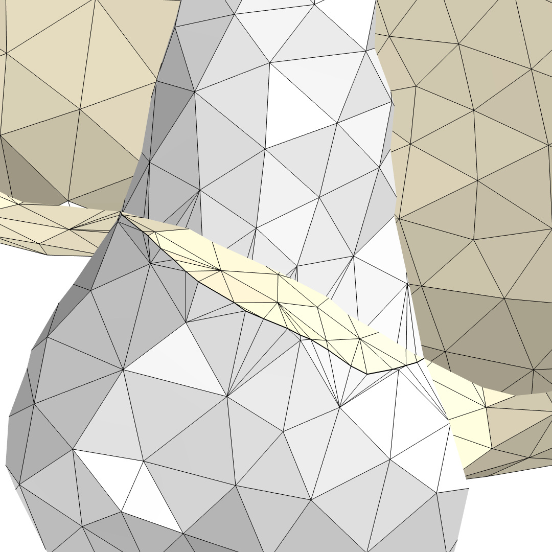
The mesh before building a Union operation: The triangles of the tooth are intersecting the triangles of the bone (left). When the Curved placement of mesh vertices option is used, the intersection edge is smoother (middle). When the Linear placement of mesh vertices option is used — as I opted to do in the example model — the intersection edge is more angular (right).
Until this point, domains had not been created inside the mesh because of the intersecting elements between the teeth and bone. Now that the intersections in the mesh were resolved, I used the Create Domains operation to form the computational domains inside the watertight regions. To get a visual of the domains, you can right-click anywhere on the mesh in the Graphics window, select Clipping and then Clip Plane. Then, in the Graphics toolbar, click the Clipping Active button and select Show Cross Section.
An alternative way to see whether the domains have been created is to check if the Selection List reports any domains. After the Create Domains operation has been built, the Graphics window should show cross-sectional faces for the domains (following image at right), the Selection List should be populated on the domain level, and the Information section of the Create Domains operation’s settings will list the number of created domains as well as the total number of domains.
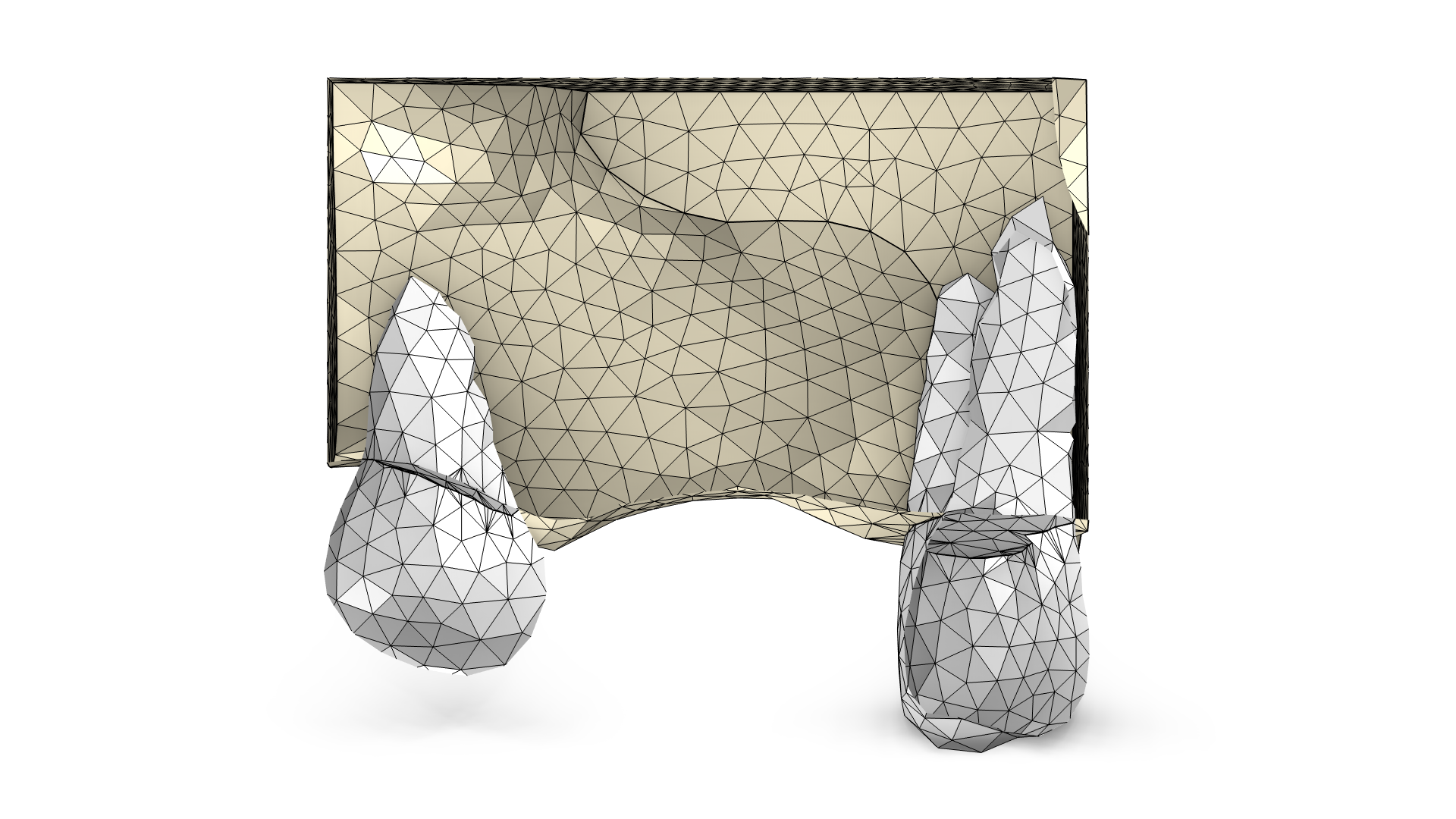
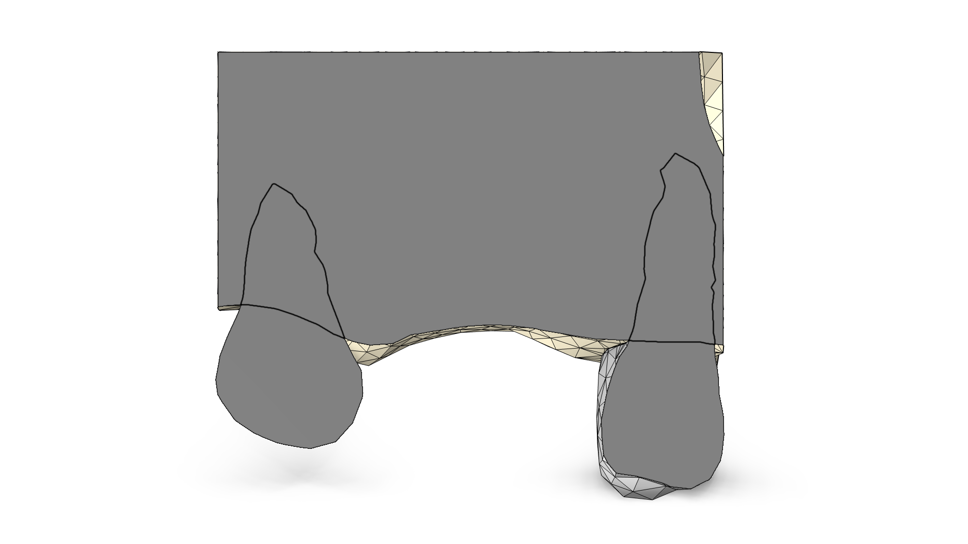
Before building the Create Domains operation, there are no domains in the mesh — only boundaries, edges, and vertices (left). After the Create Domains operation has been built, the domains are visualized with cross-sectional faces in the Clip Plane if the Show Cross Section setting has been enabled (right).
Meshes imported using several Import nodes are treated the same way as different objects are treated in the Geometry sequence when using the Form Assembly method. To connect touching boundaries in such meshes, it is recommended to use the Merge Entities operation. This operation can also be used to collapse gaps in a mesh, as shown in the following example, which is taken from the STL Import Tutorial Series. Download the application files to learn more.
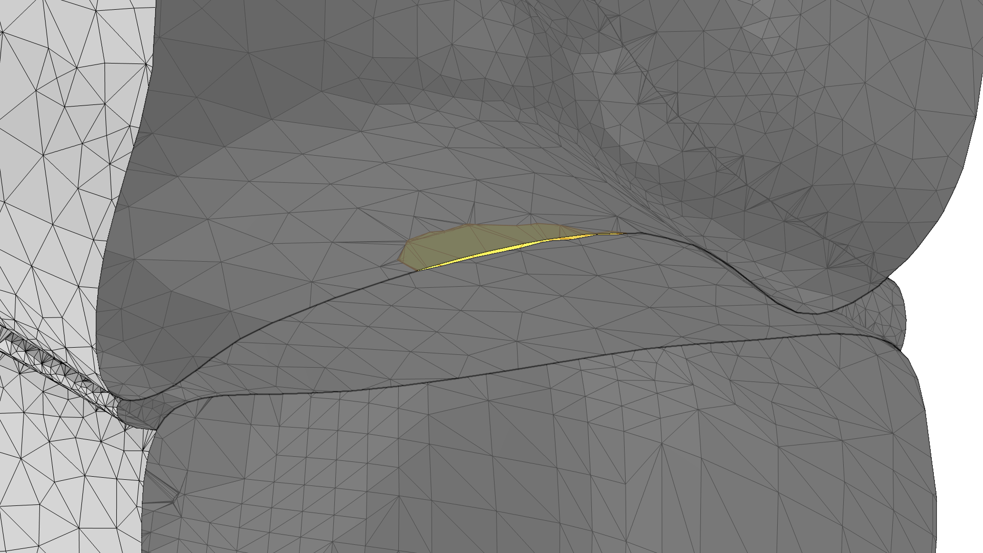
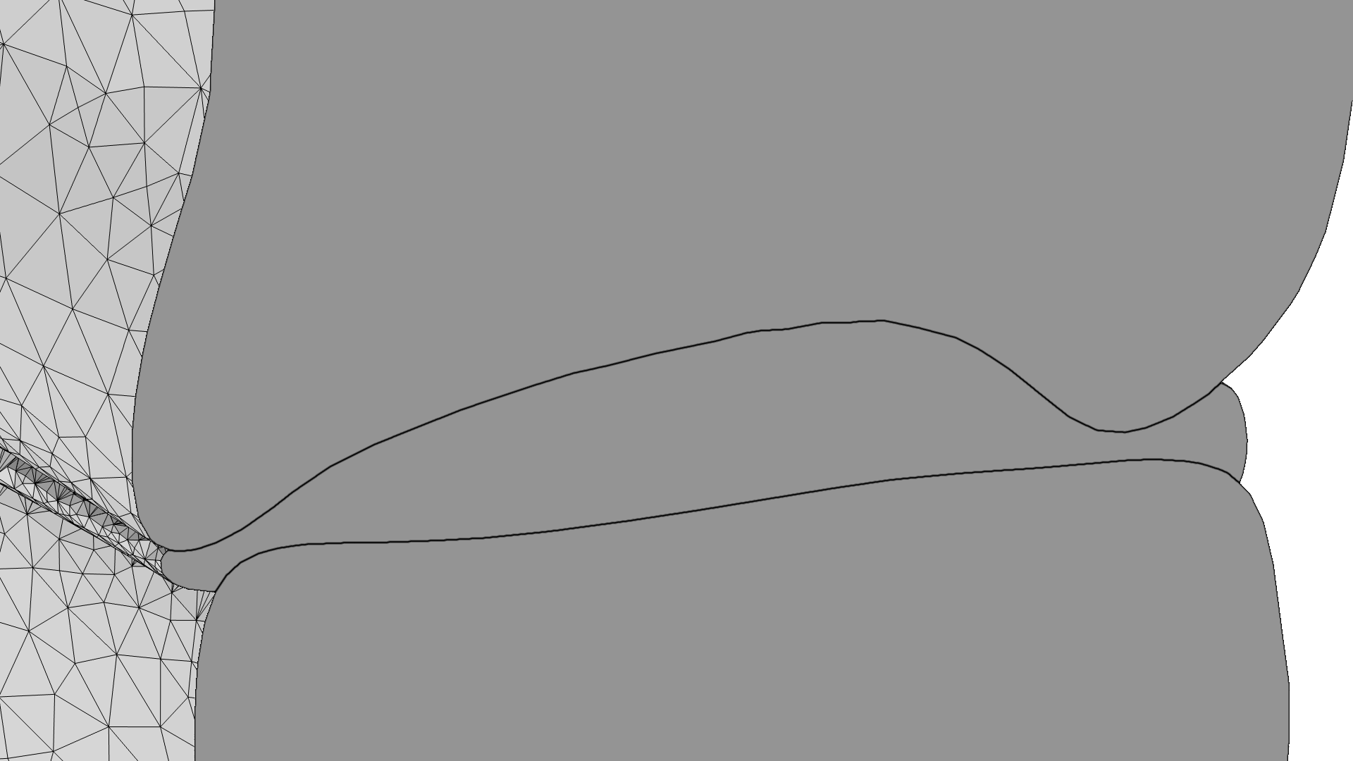
Merging two faces (yellow) to seal a gap between a vertebra and disc (left). The resulting mesh after the gap has been sealed (right).
Joining Domains and Creating Selections
As expected, the domains of the teeth in the example mesh were partitioned with the surface of the bone (following image at left). I could have kept the domain partitioning as it was, but instead I used the Join Entities operation to join the domains of the teeth into two domains (image at right). After that, I could define domain and boundary selections to be used when setting up materials and physics. For this example, I created domain selections to facilitate assigning material properties.
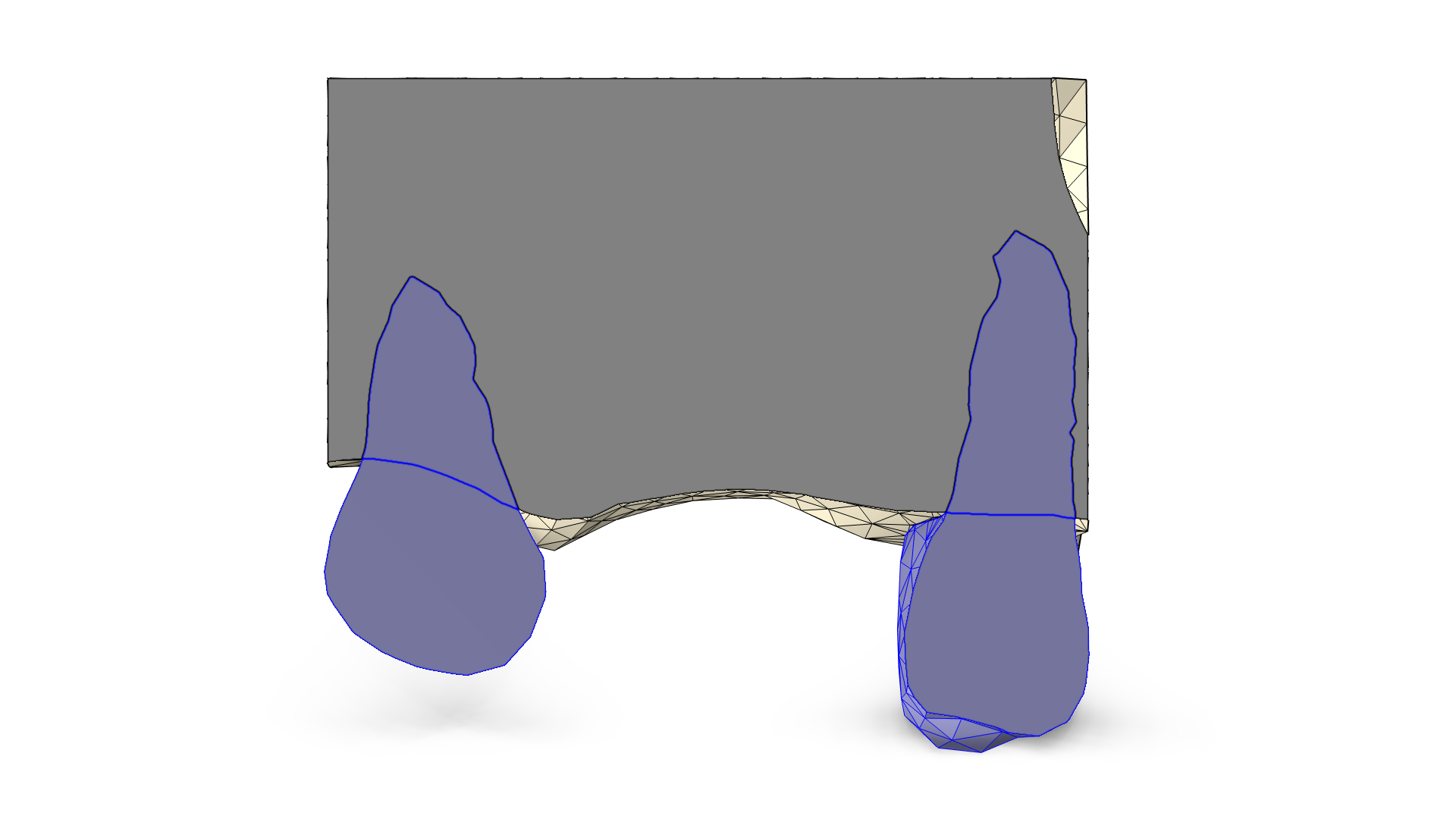
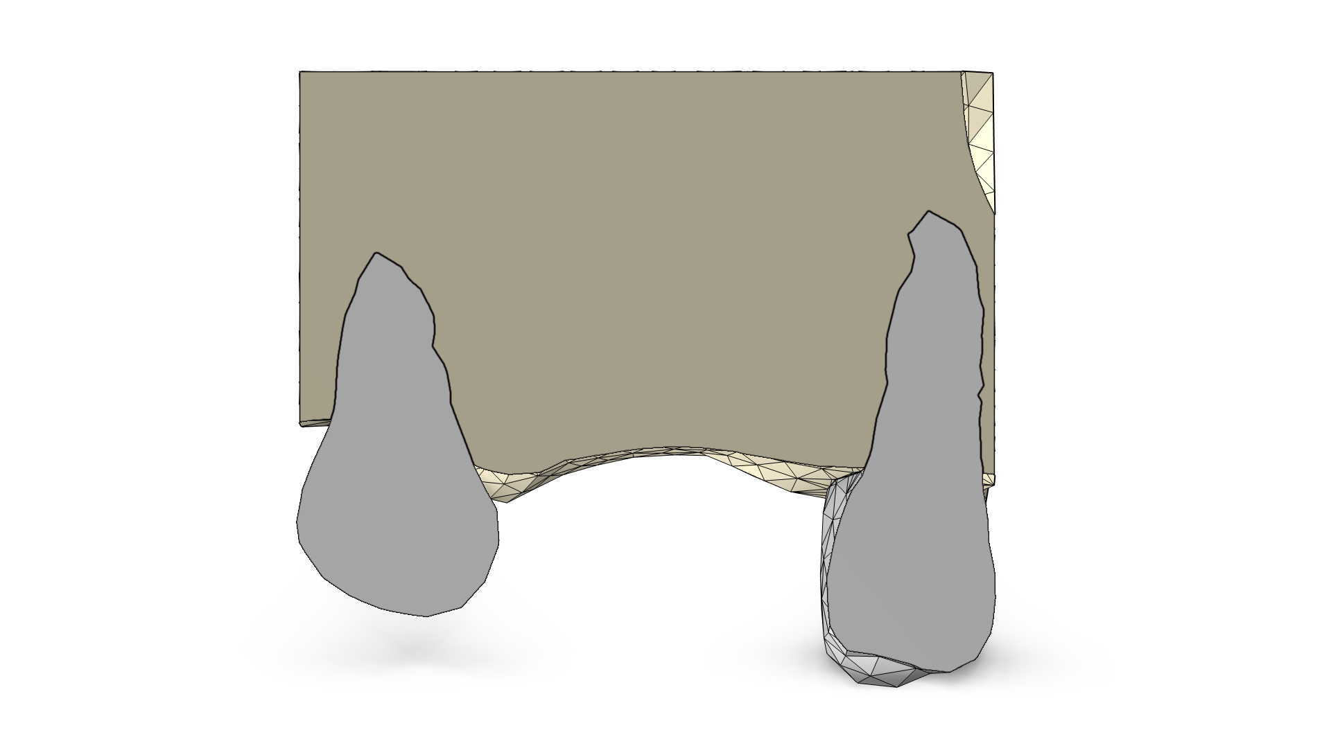
Joining the domains of the teeth (left). The domains with assigned colored selections: Now that the domains have assigned colors, the cross section also shows these colors (right).
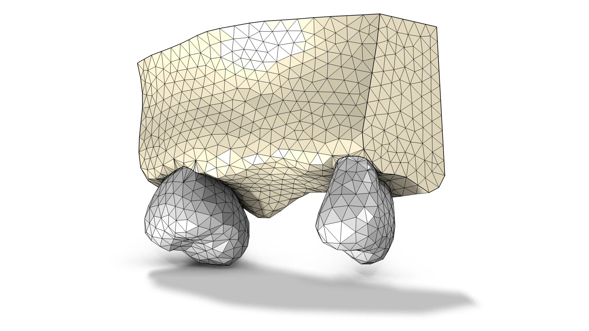 The final mesh-based geometry.
This mesh-based geometry can very well be used for simulation at this point; all that’s needed is to build the computational mesh in the Mesh 1 node.
Concluding Thoughts
COMSOL Multiphysics® offers multiple features to repair and edit imported meshes. In this blog post, I have demonstrated how to rotate an imported mesh, remove elements, merge entities, unite meshes, and create computational domains. If you haven’t already, check out the model file of the example featured in this post. Note that all edits done for this mesh may not be necessary for other meshes. The order in which you add the operations can also differ, depending on the mesh at hand. I have prepared this mesh to later add a dental implant where a tooth is missing, and the idea is to generate a computational mesh that could be used for a solid mechanics simulation. The topic of combining the mesh prepared in this blog post with imported CAD geometry is covered in Part 2 of this series.
Learn More
If you are interested in learning more about working with imported meshes, check out these resources:
- Watch this video on editing and repairing imported STL meshes and combining them with CAD geometry.
- STL Import Tutorial Series, a tutorial model series showcasing how to repair, edit, and combine STL meshes with each other and with geometry created in the software
- Analyzing Porous Structures on the Microscopic Scale, a tutorial model that showcases import of an STL file and the generation of a physics-controlled mesh
- Spray Particle Deposition in Human Airways, a tutorial model featuring the Mesh Partition with Ball add-in to repair the STL mesh
- Generating a Simulation Mesh of a Femur From 3D Data, a blog post showing two ways of creating a mesh from data in a file and smoothing the shape of the meshed surfaces
Reference
- kbrowne, “Skull and Eyes – Visible Human Male. Version 1.03,” NIH 3D, 12, Apr. 2026; https://3d.nih.gov/entries/3DPX-020591.




Comments (0)