
Today, even though most of us aren’t celebrities, we appear on camera more than ever before. Smartphones, computers, and other devices equipped with compact camera modules (CCMs) are almost inescapable — whether or not we feel ready for our closeups! As CCM-equipped products continue to rapidly evolve, these small but powerful optical devices must also keep improving. To ensure that CCMs can produce clear, sharp images within cost and spatial constraints, engineers can analyze their performance with optical ray tracing simulation.
Factors that Help Define Camera (and CCM) Performance
Even the most advanced compact camera modules share some key attributes with traditional cameras and other optical systems. An optical system is defined by the shape of its geometry — the position, orientation, thickness, and curvature of the lenses, mirrors, apertures, prisms, and so on — and by the materials used in its construction. To analyze an optical system, designers seek to quantify the departures from an ideal system, called aberrations. To understand the distinct challenges of CCM design, it helps to consider some of these factors in more detail.
Spherical Aberration
The speed of light depends on the medium it is passing through, such as glass, plastic, water, or the air. If the medium has uniform properties throughout its volume, light will propagate through it in straight lines. When light hits a surface where different materials meet, its direction will change. This redirection of light’s path is called refraction, and when a lens refracts light, it can lead to distortion in the resulting image. When the surface of a lens is curved uniformly, like a section of a sphere, it causes a distortion that’s called spherical aberration.
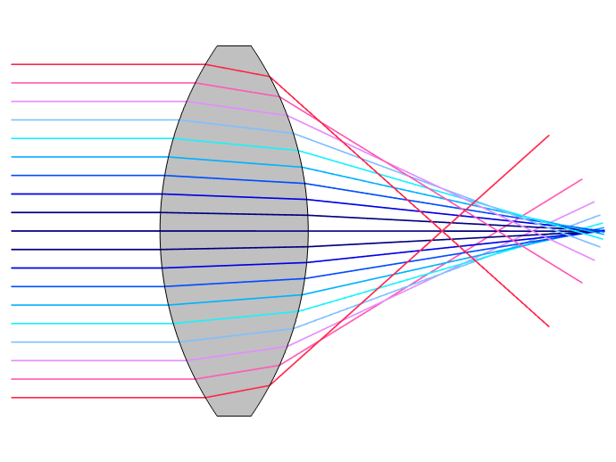
Light rays passing through the edges of a spherical lens will be directed toward different focal points than light passing through the center. To counter this spherical aberration, lenses can be made aspheric and/or combined with other lenses to redirect light to the desired point on the image plane.
Spherical aberration occurs because light passing through the edge of a spherical lens has a different focal point than light passing though the center. This will cause blurring in the resulting image. To counteract this effect, the curvature of a lens’s surface can be varied to redirect light and maintain clear focus. As the varying curve profile of such a lens is no longer spherical, this is called an aspheric lens. Another method for reducing spherical aberration is to use multiple lenses to achieve a desired magnification. Cameras will often feature multiple elements to achieve the clearest possible image within physical constraints on the size of the device.
Focal Ratio
In any optical system, the ratio of focal length f to objective diameter D is the focal ratio, which is commonly called the f-number in photography. (See an illustration of these concepts below.) The f-number has a direct impact on an image’s depth of field. A lower f-number, indicating a larger aperture relative to focal length, will reduce the depth of field. This means that even when part of an image is in clear focus, other objects that are further or closer to the lens will appear blurry. If we keep the focal length the same but reduce the aperture, our system will capture a smaller, sharper overall image.
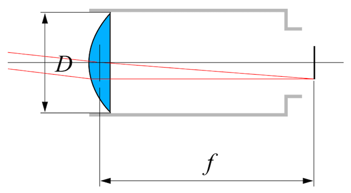
Focal ratio is an important parameter of on optical system’s performance. Its value is defined by the ratio of focal length f, which is the distance between a lens and the image viewing surface, to objective diameter D. Image by Vargklo, in the public domain via Wikimedia Commons.
The dimensions that affect focal ratio are made apparent by the cameras used for photographing wildlife and sporting events; they often have wide lenses that are also remarkably long, in order to capture as much of a scene as possible with the greatest depth of field.
From Camera to CCM: An Optical Design Evolution
While a modern compact camera module shares many core elements with its ancestors, it’s also subject to additional design constraints. The most significant constraint is highlighted in its name: a compact camera module must be compact. As CCMs are often integrated into mobile phones, tablets, and other portable products, their lens assemblies are usually smaller and lighter than those of conventional cameras. As the market for electronic devices can be highly price sensitive, manufacturers also face pressure to keep the cost of a CCM as small as its dimensions.
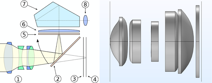
Left: Schematic of the parts of a typical digital single-lens reflex (DSLR) camera: 1. Lens assembly. 2. Mirror. 3. Focal-plane shutter. 4. Sensor/film. 5. Focusing screen. 6. Condensing lens. 7. Pentaprism or pentamirror. 8. Eyepiece. Image by Cburnett. Licensed under CC BY 3.0, via Wikimedia Commons. Right: Compact camera module lens assembly as defined by a tutorial model constructed in the Ray Optics Module. Many of a DSLR’s optical components are not included in a typical CCM.
All of these factors are reflected in the design and construction of CCMs, especially when compared to the common digital single-lens reflex (DSLR) camera design. A DSLR will usually combine a detachable lens assembly with an image sensor the same size as a frame of 35 mm film. It will also include an arrangement of mirrors leading to a viewfinding eyepiece mounted above the lens/image sensor assembly. This enables the photographer to see the exact image being captured by the camera.
On a CCM, some of these components are reduced in size while others are left off entirely. For example, there’s no viewfinder assembly. The module’s image sensor is smaller than 35 mm, and the individual receptors or pixels that cover the sensor’s surface are also smaller. (This is why comparing the megapixel values used to describe digital cameras can be misleading — not all pixels are the same size!) A CCM’s lens assembly is small both in diameter and thickness, as it cannot protrude from its housing like that of a DSLR. Also, some or all of its lenses are made from plastic, rather than glass, to reduce cost and weight.
Coping with the Constraints of CCM Design
Design constraints make image sharpness difficult to achieve in a CCM. For example, on a DSLR camera with a large protruding lens assembly, the focal ratio can be tuned by physically adjusting its focal length and stopping down its aperture. However, on a CCM, it is not practical to stop down its aperture further (due to its already small size). This means that light rays bend more sharply as they travel through a CCM assembly, adding potential distortion in the resulting image.
How can CCM designers make the most of small plastic lenses, packed tightly together with a limited range of adjustment? As described above, both the shape and quantity of lenses can be used to optimize performance. The compound curves of glass aspheric lenses are typically more expensive to produce than those with regular curvature, but here, the use of plastic is actually an advantage. Plastic lenses can be produced in large quantities from a single mold, avoiding the costly and time-consuming process of grinding glass lenses into aspheric shapes.
Along with these positive effects, aspheric optical elements introduce more complexity into the task of optimizing system performance. In a research article published in 2012, engineers at Carl Zeiss said:
“CCM designs are primarily driven by high aspheric aberration correction to achieve size and cost restrictions. Proper sampling in pupil and field coordinates is therefore necessary to control higher order aberration contributions…The large number of highly aspheric surfaces led to an increase in misalignment sensitivities for CCMs. Thus, technological requirements are correspondingly demanding.”
Optical ray tracing is a valuable tool for tuning the behavior of CCMs’ tightly packed, highly aspheric lens assemblies.
Accounting for Aberrations with Simulation
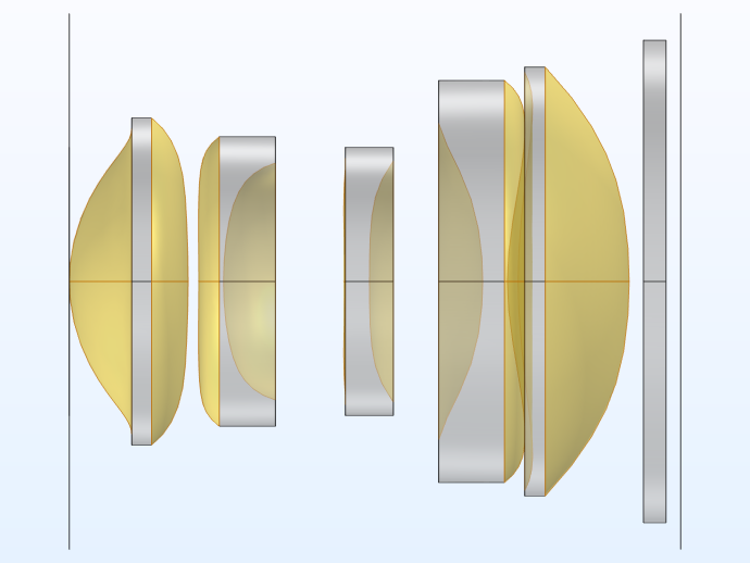
A model of a five-element (plus filter) compact camera module assembly can be constructed using the Aspheric Even Lens 3D part from the Ray Optics Module part library. This model supports ray trace analysis to identify and visualize potential aberrations that affect image quality in a CCM. As shown below, the assembly modeled in this tutorial has a 7.0 mm focal length and an f/2.4 focal ratio.
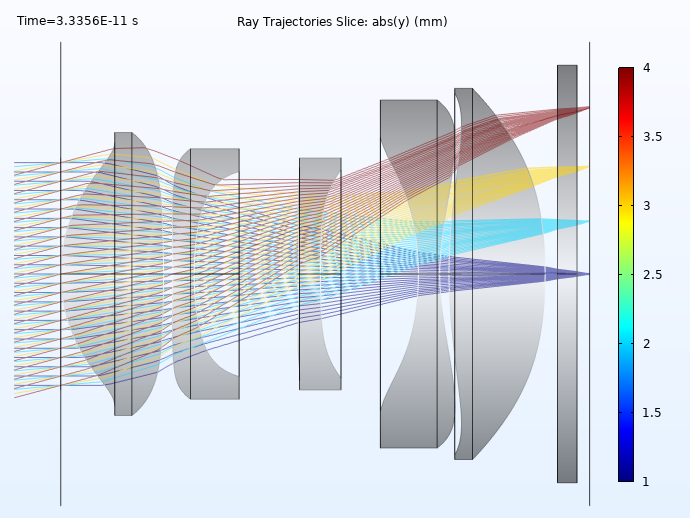
An overview of the Compact Camera Module optical design. In this cross-sectional view, the rays have been colored by release index.
The ray tracing algorithm used by the Geometrical Optics interface computes the refracted ray direction based on a discretized geometry via the underlying finite element mesh. The aspheric surfaces of the compact camera module have been assigned to a cumulative selection on which the mesh has been refined.
Note that the representation of curved boundary elements in COMSOL Multiphysics can actually be set to different shape orders. For example, the software can treat the boundary elements as piecewise cubic or quartic polynomials to increase accuracy. This helps to offset the discretization error that can otherwise occur when going from the optical prescription to the mesh representation of the lens system.
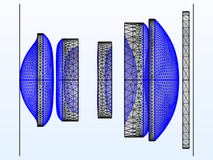
Left: Cumulative selection of the lens surfaces for the CCM model. Right: Aspheric surfaces on which the mesh has been refined.
The ray diagram and spot diagram for the CCM are shown below. The lens surfaces have been rendered using an expression based on the material refractive index, and the rays have been colored according to the radial distance from the centroid of each release at the image plane. In the spot diagram, the rays are colored according to their radial distance from the center of the entrance pupil. This provides a way to visualize the origin of the most aberrant rays.


Left: Ray diagram of the CCM, where the rays are colored by their radial distance from the centroid on the image plane. Right: Spot diagram colored according to the radial distance from the center of the entrance pupil.
Take a Closer Look at the Compact Camera Module Tutorial Model
To further explore the potential for optimizing the performance of CCMs, you can try modeling one yourself. Download the tutorial model featured here by clicking the button below:


Comments (0)