
Hearing aids are designed to manage different types of hearing loss, and in order to maintain their functionality, proactive maintenance is essential. Acoustic engineers and designers integrate wax guards into hearing aids to protect the miniature loudspeaker (commonly called the receiver in hearing aids). Using the COMSOL Multiphysics® software and the transfer-matrix method, engineers can analyze the small dimensions of a wax guard and simulate faster acoustic responses.
Utilizing Wax Guards for Hearing Aid Maintenance
When it comes to our ears, we naturally produce earwax that acts as a natural cleanser and a protective barrier to trap foreign debris. However, earwax and hearing aids isn’t the best combination, as it can result in blockage and cause distorted sounds for the user.
Preventive precautions can be taken in order to avoid hearing aid malfunctions, such as using a wax guard to trap wax and moisture from infiltrating the hearing aid. Using a wax guard is one cost-effective approach that can help improve the functionality and overall lifespan of a hearing aid.
A wax guard is a small, replaceable protective mesh that is used for receiver-in-the-ear (RITE) and receiver-in-canal (RIC) hearing aids. The figure below shows the assembly of a hearing aid and the location of the wax guard. The miniature loudspeaker, also referred to as a receiver, is powered through the wire that is connected to the main body of the hearing aid, located behind the ear of the user. The wax guard is placed in a small structure that can be removed and replaced. Using COMSOL Multiphysics and the Acoustics Module, we can analyze the small dimensions of a wax guard and their acoustic properties with features available as of version 5.5.
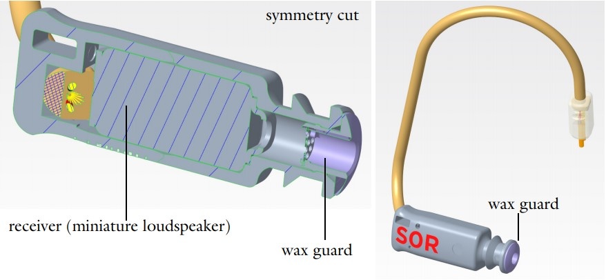
Illustration of the receiver assembly and location of the wax guard. S0R stands for the type Small, of length 0, and Right ear. The pictures are copyright by Widex.
Modeling the Imported CAD Geometry of a Wax Guard in COMSOL Multiphysics®
This tutorial is completed in two parts:
- Computing the transfer matrix of the wax guard using the Port boundary conditions and Port Sweep functionality
- Computing the response of the wax guard in a typical measurement setup and comparing it to actual measurements
The transfer matrix computed in Step 1 is used in Step 2, where a lumped transfer matrix approach is set up within COMSOL Multiphysics.
In this model, the NanoCare™ wax guard CAD geometry, receiver transfer matrix data, coupler transfer matrix data, microphone impedance data, and measurement data are copyright by Widex. The geometry of the wax guard is shown below in different views.


Wax guard geometry. CAD geometry is copyright by Widex.
Transfer Matrix: A Lumped Representation
A transfer matrix (also known as a two-port) is a useful and commonly used method in optics and acoustics applications to analyze propagating waves through a system. In this tutorial, the transfer matrix of a wax guard consisting of an inlet and an outlet is computed; it represents a lumped model of its subsystem. Because the wax guard dimensions are small, using a transfer matrix is ideal in the full frequency range, as only plane waves will propagate (we are well below the cut-off frequency). It is important to acknowledge that because of the small dimensions, the transfer matrix representation needs to include the thermal and viscous boundary layer losses to measure how these losses affect the acoustic system. If you know the transfer matrix of all of the components in your model, simulating the acoustic response is extremely fast. This also means that it is simple and fast to study the performance of, for example, different receivers in the same system.
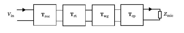
In COMSOL Multiphysics, you have the option to define matrices to set up the lumped representation of a full system (it requires a bit of work). The full measurement setup, modeled in this tutorial, consists of four two-port components in series. Each is described by its transfer matrix, for the receiver (Trec), the receiver tube (Trt), the wax guard (Twg), and the coupler (Tcp), as well as the measurement microphone impedance (Zmic). The input to the model is a voltage Vin applied to the receiver (remember, this is the miniature loudspeaker in a hearing aid). A coupler is a volume that represents a standard ear canal. All transfer matrices, except the one of the wax guard, rely on existing data (measured or provided from suppliers). The transfer matrix of the wax guard is the one computed in the first part of the model. The system is represented schematically below:
To compute the transfer matrix of the wax guard, the model uses the Thermoviscous Acoustics, Frequency Domain interface, the Port boundary condition, and the Port Sweep functionality, available as of version 5.5. When a port sweep is done, the transfer matrix of the analyzed system (here, the wax guard) is computed automatically. Because the ports assume plane wave propagation, they need to be located away from any sudden geometry changes (like the perforated plate in the wax guard). In order to do this, an inlet tube of length 1 mm is added to the geometry. The simulation domain is the air volume inside the wax guard, including the inlet tube, as shown below.
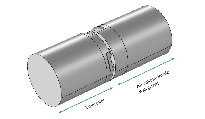
Simulation domain consisting of the air domain inside the wax guard as well as the extra inlet tube.

The Port feature Settings window, including User defined, Numeric, and Circular port type options.
Evaluating the Wax Guard Acoustics
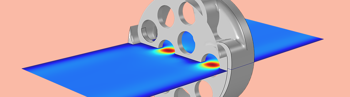
The acoustic pressure and instantaneous velocity variations are shown below. In the model, the frequency parameter and the port exciting the system can be changed (inlet and outlet). Changing the frequency parameter allows you to visualize the extent of the viscous and thermal boundary layers. The viscous boundary layer arises because the air particles cannot move at the solid boundary due to viscosity (the no-slip condition). In the plot, it is seen that the velocity goes to zero at the walls (dark blue). Viscous dissipation (damping) arises where there are large gradients in the velocity. This coincides with the perforates in the wax guard (rapid change in the color).


Pressure distribution at 10 kHz, for the port excitation at the outlet (left) and velocity distribution at 1 kHz, with the port excitation at the outlet (right).
The graph below shows the response of a typical wax guard measurement setup (depicted schematically above) and the comparison between measurements and the system that was modeled using the transfer matrix approach. It shows the sound pressure level at the microphone when the driver has a 0.1-V peak input harmonic signal. The measurements and simulation correspond well at up to about 6000 Hz. Using this approach, engineers can compare multiple setups before doing any measurements, allowing the design to be cost and time efficient. Several wax guard designs can be studied and tested virtually and the transfer matrix of the component can be stored for further analysis and comparison.
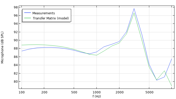
Comparison of simulation and measurements of the SPL response measured at the microphone in the coupler. The measurements are copyright by Widex.
Using the automatic transfer matrix computation in COMSOL Multiphysics, engineers and designers can test various designs of wax guards and their acoustic properties in seconds. This type of approach allows breaking down a total system into smaller subsystems for faster acoustic response analysis.
Next Step
Click the button below to try out the Wax Guard Acoustics: Transfer Matrix Computation model for yourself. This will take you to the Application Gallery, which includes step-by-step documentation.
“Widex” covers Widex A/S and Affiliates. “Affiliate” means a legal entity, now or hereafter, directly or indirectly, owned or controlled by, or owning or controlling, or under common control with by one of the Parties, but such legal entity shall be deemed to be an Affiliate only so long as such ownership or control exists. For purposes of this definition “control” of a legal entity shall mean to have, directly or indirectly, the power to direct or cause the direction of the management and policies of a legal entity, whether (a) through the ownership of voting securities entitling to the right to elect or appoint, directly or indirectly, the majority of the board of directors, or a similar managing authority; (b) by contract; or (c) otherwise. For purposes of this definition, Widex A/S, Sivantos Pte Ltd, together with their Affiliates, are Affiliates of each other.
Nanocare is a trademark of Widex.


Comments (2)
Hardik Ruparel
January 29, 2020Nicely written article.
Could you elaborate more on why you recommend using a transfer matrix in full frequency range ? and why your point on well below the cut-off frequency ?
Mads Herring Jensen
January 30, 2020 COMSOL EmployeeDear Hardik
The transfer matrix of the various sub-systems rely on a plane wave assumption (only plane waves propagate). The transfer matrix computed for the wax guard is also computed assuming that only plane waves propagate. For microacoustic systems this is a very good assumption as the cut-off frequency of the first non-plane mode is very high, for a 1 mm diameter tube it is at 200 kHz. You can see more details in this blog entry on our port conditions for pressure acoustics: https://www.comsol.com/blogs/using-the-port-boundary-condition-in-acoustic-waveguide-models/
Best regards
Mads