Acyclic generator, unipolar generator, disc dynamo, Faraday wheel: No matter what you call it, the homopolar generator is an interesting device. Unlike most generators, homopolar generators produce high current with low voltage and can store and release large amounts of electricity. Due to these abilities, scientists have worked to improve this device since its invention. To continue this work, you can evaluate the performance of homopolar generator designs using the COMSOL Multiphysics® software.
A Brief History of the Homopolar Generator
10 years after making a breakthrough in electric motors, Michael Faraday created the first electric generator in 1831. The setup for this device (later called a homopolar generator) was simple, consisting of a copper disc that rotated in between the poles of a permanent magnet. While Faraday’s generator successfully demonstrated electromagnetic induction, it was too inefficient to be practical, as the current tended to circulate backward and create counterflows.
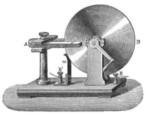
Sketch of an early homopolar generator, also known as a Faraday disc. Image in public domain in the United States, via Wikimedia Commons.
Over the years, other scientists tried their hand at improving the performance of homopolar generators. A famous example is Nikola Tesla, who developed a design in which a metallic belt separated parallel discs with parallel shafts. This arrangement helped reduce frictional losses, an important factor in enhancing their efficiency.
In the 1950s, it was discovered that homopolar generators are particularly good for pulsed power applications, as they can store energy over long periods of time and release it in bursts. This finding led to renewed interest in the generator, with scientists creating large versions of the device. One such example was built by Sir Mark Oliphant for the Australian National University. This supersized generator could supply up to 2 MA of current and was used for over 20 years.
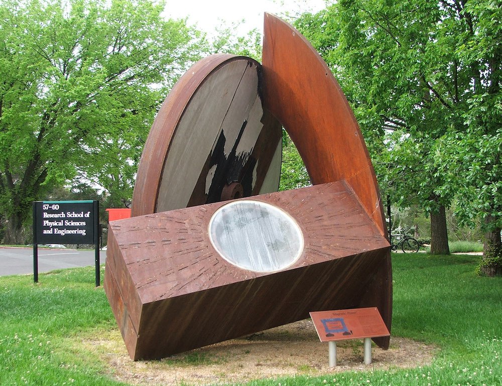
Parts of the homopolar generator created by Sir Oliphant, which has been disassembled and put on display. Image by Martyman at English language Wikipedia. Licensed under CC BY-SA 3.0 Unported, via Wikimedia Commons.
While homopolar generators have come a long way — and been called many names — since Faraday’s time, researchers and engineers are still working to improve their performance. To investigate potential designs, one approach is electromagnetics simulation…
Modeling a Simple Homopolar Generator with COMSOL Multiphysics® and the AC/DC Module
This example models a simple 3D homopolar generator, which consists of a rotating disc with a 10-cm radius placed in a uniform magnetic field of 1 T. A conductor connects the disc’s rim to the center, passing through the magnetic field and generating Lorentz currents in the disc.
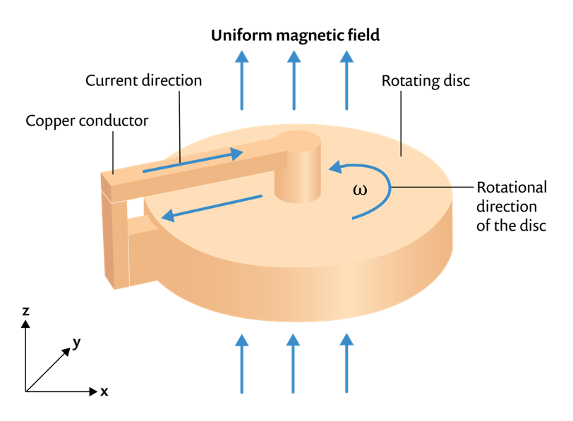
The geometry of the homopolar generator model.
Note that the angular velocity of the disc is 1200 rpm and that ~45.16 kA of current flows through the conductor.
To model the rotation of the disc, you can use a Lorentz term for two reasons:
- The disc doesn’t have a magnetic source that moves with it
- The disc is unbounded and the direction of its motion doesn’t change
Here, the current distribution stays stationary and does not follow the disc’s rotation.
Examining the Results of the Electromagnetics Simulation
After using a stationary solver, it’s possible to examine the flow of the current moving through both the disc and conductor. By looking at the current density norm and current direction, you can find ways of improving the current flow in a homopolar generator design.


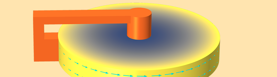
Current density norm (left) and direction of the current (right) in the conductor and disc.
In addition, it’s possible to examine the effect of the magnetic field on a design, such as how it affects rotation. As an example, you can see the total and induced magnetic flux densities below.
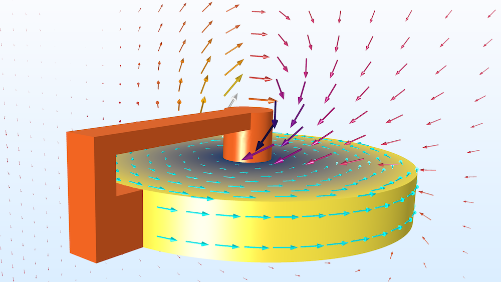
The homopolar generator causes perturbations in the B-field as shown by the arrow plot in the volume surrounding the generator. The wheel velocity is shown with arrows and colors on the surface.
Since resistive losses play a key role in the efficiency of these generators, it’s important to minimize them as much as possible. As can be seen in the image below, simulation provides a way to determine the losses in the conductive parts of a generator design.
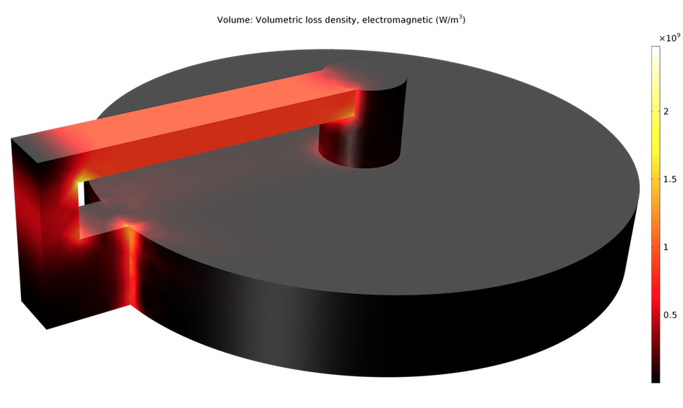
The resistive losses in the disc and conductor.
Using electromagnetics modeling, engineers can improve homopolar generator designs, enhancing their performance by reducing frictional losses or altering the magnetic field.
Next Steps
To get started with modeling homopolar generators, click the button below. Doing so will take you to the Application Gallery, where you can sign into your COMSOL Access account and then download the MPH file and tutorial documentation for this example.
Further Reading
- Learn more about modeling generators and motors on the COMSOL Blog:
- See what else you can model with the AC/DC Module


Comments (0)