
Learning from the Two-Capacitor Paradox: Do Capacitance and Inductance Exist?

The two-capacitor paradox is a provocative thought experiment set up to expose some of the limitations of electrical circuit modeling, and many different ways of resolving the paradox have been devised. I’ll add a solution to the mix that can be modeled in the COMSOL Multiphysics® software and then expand upon it to ask, and answer, an even more provocative question: Do capacitance and inductance exist? Let’s dive in!
The Two-Capacitor Paradox
This thought experiment is usually presented as: Consider a device composed of two equivalent capacitors, with capacitance, C, connected in parallel with an open switch between them. All of the wires and capacitors are made of ideal, perfectly resistance-free, lossless materials. One of the capacitors is charged to a potential, V_i, so the charge stored is Q = CV_i. There is no potential difference on the other capacitor, so it has no stored charge. What happens when you close the switch?
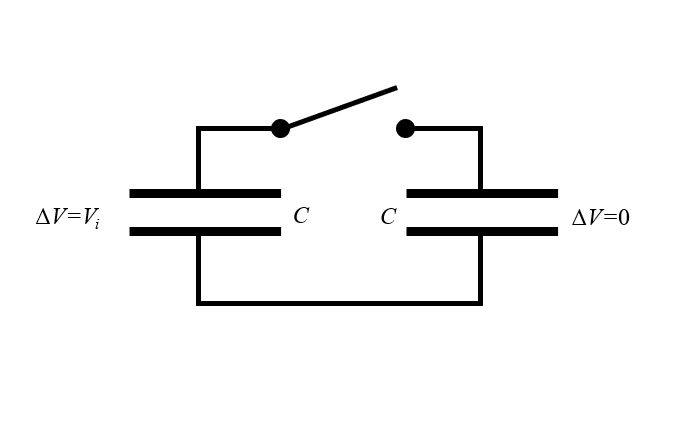
Schematic of the two-capacitor paradox. One capacitor has a potential difference between the plates. What happens when the switch is closed?
Some presentations of this thought experiment will throw in a red herring and claim that the charge on the first capacitor will flow into the second, reducing the potential difference on the first and increasing it on the second until a steady state is reached — at which point the potential difference is the same on both capacitors and half of V_i, since the same charge, Q, is now spread across two equivalent capacitors. This immediately leads to a paradox, though, because the energy in each capacitor is W_C = \frac{1}{2} C \Delta V^2. If the initial energy is \frac{1}{2} C V_i^2 and the final energy is 2 \frac{1}{2} C\left( V_i/2 \right)^2 = \frac{1}{4} C V_i^2, where did the other half of the energy go?
There are many solutions available that invoke everything from quantum mechanics to thermodynamics. These solutions are likely all valid from an educational point of view. However, many of them make an implicit appeal to reality by saying that the wires and capacitors simply must have some resistance or must have some inductance. But why? At least within the context of a thought experiment, it may be reasonable to assume perfectly lossless materials, thus neglecting resistance. But what about the inductance? Within the context of this thought experiment, can we neglect inductance? Let’s follow this question and see if it provides an interesting answer…
A Simple Solution to the Paradox
Our device is composed of two ideal, lossless capacitors. But even an ideal capacitor must spatially separate its charges. That is, a capacitor must have some size. And if each capacitor has size, then it must be separated by some nonzero distance from the other capacitor. So if we redraw our diagram just a little bit, we see that we have two capacitors and two finite-diameter half-loops of lossless wire, along which a time-varying current can flow. But what do we call such a structure? An inductor!
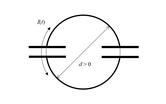
The paradox can be resolved by realizing that the structure must have a nonzero size, with current flowing around a loop of finite area, and is therefore also an inductor.
The structure that we have drawn here must have finite size, and hence it must also have inductance, as long as it exists within our universe, where free space has magnetic permeability. So simply as a consequence of there being a capacitor in our circuit, there must also be an inductor in the circuit. Actually, it gets even better: If we have an inductor, even a lossless one, any time-varying current flowing through it will lead to an electric field that exists between the turns of the inductor, and thus any inductor that we add to this circuit also acts as a capacitor! We could follow this train of logic infinitely, but for our purposes it is sufficient to merely modify our circuit with a single inductor that has an inductance, L.
We now have an LC circuit, and this has an analytic solution that immediately clears up the paradox: Current will flow back and forth between the capacitors and along the finite-length wires, oscillating at a frequency given by: f=1/(2\pi\sqrt{LC}). There will never be a steady-state solution, so we can never evaluate the electrostatic energy alone. We also have to consider the energy due to the moving charges, i.e., the flow of current, I, and this is given by: W_L = \frac{1}{2} L I^2. The sum of this electric and magnetic energy (\frac{1}{2} L I^2 + \frac{1}{2} C V^2) will not change over time.
Verifying in the COMSOL Multiphysics® Software
It is straightforward to build a model that verifies this situation using COMSOL Multiphysics® and the RF Module. We will do so using the Electromagnetic Waves, Transient interface along with the Electrostatics interface to compute the initial conditions. We will model a small region of perfect vacuum with the capacitors and wires inside. The capacitor plates, wires, and space around our volume are all treated as perfect electric conductors, which means that the electromagnetic fields will not penetrate through any boundaries. There is a guide to setting up such capacitive-discharge models in our Learning Center article: “Modeling Capacitive Discharge”.
Solving this time-domain model and evaluating the total electric and magnetic energy shows the expected oscillatory behavior. It is also possible to partition the modeling domain into different regions to evaluate the total energy in the regions around the two capacitors as well as in the surrounding space. This plot shows how the energy oscillates in space as well as time.
Animation showing the currents on the surface of the capacitor plates and wires as well as the magnetic field in the space in between.
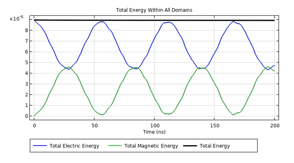
The total electric and magnetic energy oscillate over time; the sum does not change in this lossless device.
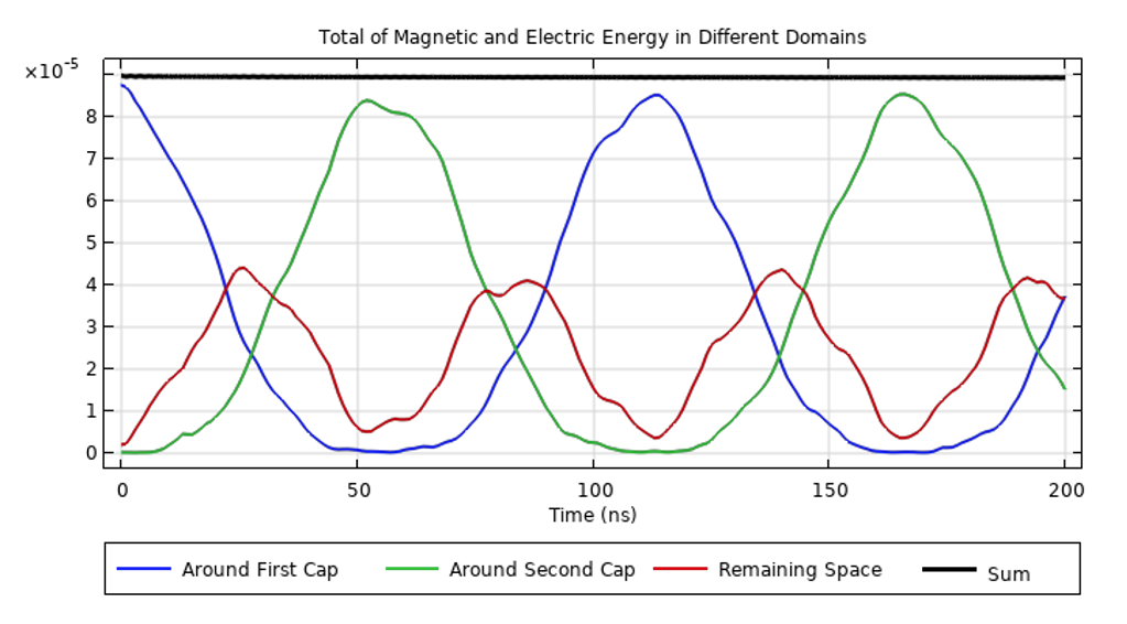
The total of the electric and magnetic energy in different domains shows that the energy oscillates in time and space.
We can observe that these plots are not purely sinusoidal in time, and we should ask why that is. Where does this higher-frequency content, i.e., the ripples in the energy over time, come from? They arise from the structure. It is quite clear that the two plates have a well-defined capacitance, but there is also a charge separation due to the wires, and this whole structure sits within a cylindrical cavity that has a resonant frequency. All of these various parts of the device have some contribution to the electromagnetic behavior. Each contribution might be quite small, but it does always exist when we consider a finite-sized structure.
Asking More Questions: Do Capacitance and Inductance Exist?
It is now time to ask a more provocative question about this (or any other) electromagnetic device: Does it have a capacitance or inductance? We have clearly seen that this particular device has both. But what if we modified it by adding a very strong dielectric material between the capacitor plates? That would make the capacitance much larger but leave the inductance unchanged. And if we made the capacitance much larger, could we say that the inductance does not matter?
In short: No, we should never think of an electrodynamic device as being purely capacitive or purely inductive. In an electrodynamic device, there will always be electric energy due to spatial separation of charges and magnetic energy due to movement of charges. Although we can sometimes construct hypothetical situations where one or the other can be ignored, we always have to remember that we are making a mental simplification.
Furthermore, all real materials also have some finite resistance, so, to be more realistic, we should speak of everything as having an impedance — and this is where we sometimes get ourselves into even more trouble. When dealing with a frequency-domain model, there exists a very familiar expression for the impedance of an electrical device:
The resistance, R, in this expression is a measure of how the kinetic energy of the moving charges, i.e., the current, is converted into thermal energy.
This equation is immediately recognizable as relating to a single-degree-of-freedom, damped harmonic oscillator, which is one of the most well-studied problems in engineering and physics. We know that we can compute from this expression the resonant frequency and quality factor of such an oscillator, and we know that real devices have a fundamental resonance and quality factor. This tempts us to equate the two and try to reduce a real-world, finite-sized, electrical device to a single resistance, capacitance, and inductance. This is a conceptual mistake and is never valid because the above expression for impedance is only applicable to a device that has infinitesimal size.
Any real device has finite size, and when it is operating at resonance, the electric and magnetic energy vary in space and time, as we saw from the plots above. Therefore, an equivalent circuit model requires at least three nodes, although sometimes many more. Turning our thoughts back to our physical model of the two capacitors and positing that the plate of each capacitor is represented by a node in the electrical circuit, we can see that the equivalent circuit model would need to be at least as complicated as the circuit pictured below, with four nodes. Note that a small capacitance has been added in parallel to the inductance of the wires since there is a separation of charge along the wires as well.
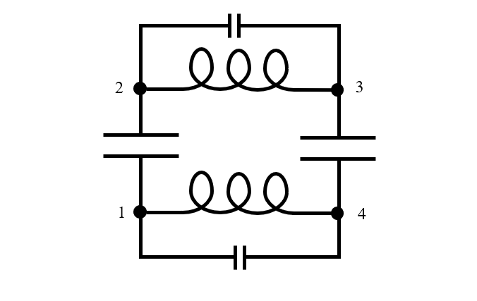
An equivalent circuit model of two finite-sized lossless capacitors connected in series.
We can hopefully see from this example that constructing an equivalent circuit model that is valid near resonance can quickly become very involved, requiring physical insight, a good bit of experience with similar devices, and numerical modeling.
Circling back to the original question, it could be argued that capacitance, inductance, and even resistance are concepts that do not exist on their own — that they exist only in combination with each other. Although we can sometimes reduce the frequency-dependent impedance of a device down to a single resistance, capacitance and/or inductance, such simplifications are only valid at frequencies below the device’s resonance. Keeping this in mind helps us avoid all manner of pitfalls, ranging from this entertaining two-capacitor paradox to much more frustratingly complex real-world problems.
Closing Remarks
We have used here a classical thought experiment to understand why the impedance of an electromagnetic device operating near resonance cannot be decomposed into a single equivalent resistance, capacitance, and inductance. Thought experiments like the two-capacitor paradox are valuable for broadening our understanding of electromagnetics and interpreting the results of our computational models.
Further Reading
Interested in learning how modeling and simulation can be used to solve other brainteasers? Check out some other examples on the COMSOL Blog:


Comments (4)
alexP
March 21, 2024Hi Walter,
This is an enjoyable topic, thank you! I will add a couple off-hand comments based on my long history with this topic.
1) Many basic courses state that all electrical circuits are an abstraction, and those with lumped parameters are even more so. The real world is fields. However, such abstractions are extremely useful, in many cases approximating (measurable) reality with very high accuracy.
2) two caps paradox is treated in detail in many texts in a lumped circuit approximation. In English, a good example is a didactic paper “Condenser Problem”, by Charles Zucker, American Journal of Physics 23, 469 (1955); doi: 10.1119/1.1934050 View online: http://dx.doi.org/10.1119/1.1934050
3) in the same vein, Including a must-be switch, and neglecting the inductance, which is the case for large C, fast switches, one sees that the losses (1/2 of the initial stored energy) are in the switch. This is given by a rigorous circuit analysis with switching time tending to zero, and I tend to think that Comsol will calculate the same.
4) In practical applications if there is need to transfer energy from C to C, an inductor is used in series with the switch. In magnetic compressors, nonlinear (saturable) inductors serve as switches.
Walter Frei
March 21, 2024 COMSOL EmployeeHello Alex,
Yes, I very much agree, using lumped parameter electrical circuit models can be a very useful abstraction, as long as we remember that we are doing so. My experience is that sometimes people forget that they are making an abstraction, and then they get themselves into great conceptual difficulties that can be difficult to unwind.
Zucker’s solution is indeed interesting, although he implicitly assumes the resistance is sufficiently large to ignore the inductance, and I have some quibbles with doing so.
Per Sundqvist
March 22, 2024Nice and well explained model and nice movie:)
There is a nice general expression of the RCL-circuit:
it=U0/L*exp(-t/t1)*sinh(omega*t)/omega
where:
omega=sqrt(-1/L/C+(1/t1)^2)
t1=2*L/R
U0 is the initial voltage over the capacitor C.
For different R,C,L the omega could become imaginary and sinh->sin
The solution goes from damped pulse to oscillating.
From the expression you could do “limit” calculation, for example what happens if L->0 or R->0 etc.
But as other have said, the real physical circuit distributed in space is sometimes more complicated than the RCL-circuit. Yo may add array-network of inductors and capacitors (you can derive wave solution from these periodic structures also with potential progressing with near speed of light) if you want to model it by a lumped circuit model, or you use COMSOL:) In extremer RF-case you also have EM-radiation of energy (i.e., antenna) that I guess is difficult to model in lumped circuit model.
Walter Frei
March 22, 2024 COMSOL EmployeeHello Per,
Yes, a series RLC circuit model (the three components in a triangular arrangement with three nodes) can be an appropriate as long as the resonant frequency of the circuit is much, much lower that the resonant frequency of the inductor as well as the resonance of the capacitor. (That is the case that we likely all studied in our “Intro to Circuits” laboratory at university. )
At the opposite extreme; the ringdown of a shorted inductor can never be modeled with so simple a circuit. At least four nodes are needed, or even better: A full fidelity finite element model 😉 !