

Vertical-axis wind turbines (VAWTs) offer many advantages over the more traditional horizontal-axis wind turbines (HAWTs). Still, VAWTs come with their own set of challenges, including low peak efficiency. One way to address these issues is by using pitch control systems, which can be optimized to improve the efficiency and energy generation of VAWTs. Let’s explore simulation research into optimizing an airfoil pitch control system for a VAWT via the COMSOL Multiphysics® software and add-on CFD Module.
Comparing Horizontal-Axis and Vertical-Axis Wind Turbines
Wind turbines (not to be confused with windmills) were first used to generate electrical power in the 19th century. Scottish innovator James Blyth is largely credited with this invention. Supposedly, Blyth used a wind turbine to generate electricity for his cottage. He later improved the design to provide power to a nearby asylum.
Different types of VAWTs compared to the operation of a HAWT.
The use of wind-generated electrical power is continuously increasing. To help with the growing demand, engineers must ensure that wind turbine designs are highly efficient. This is a particular challenge for VAWTs, which struggle with peak efficiencies and starting torque, among other issues. On the other hand, VAWTs have several benefits. For instance, they are easier to install and maintain than HAWTs and don’t need to point windward. VAWTs can also be used in urban areas and in smaller scales and are a low risk for humans and wildlife.
To overcome the shortcomings of VAWTs while harnessing their advantages, we can use pitch control systems. These systems improve the starting torque and efficiency and provide a broader operating range than traditional fixed-pitch VAWTs.
Let’s explore simulation research from a team at Sam Houston State University and Southeastern Louisiana University that examines how airfoil pitch control affects the efficiency of a VAWT.
Analyzing a Vertical-Access Wind Turbine with CFD Simulation
The researchers investigated a dynamic control system that contains both pitch and camber controls. This system is comprised of three blades (or airfoils) with flaps at the trailing edge. At the center of the system is a vertical-axis hub that is attached to blade-supporting arms. Each airfoil is connected to one of these support arms and freely pivots with respect to the arm. The independent pivoting enables the airfoils to have adjustable wind attack angles.
With an airfoil pitch control system, the angle between the support arms and airfoils can be altered for any given support arm position. This changes the attack angles between the wind and airfoils, redistributing the air pressure on the airfoil surfaces.
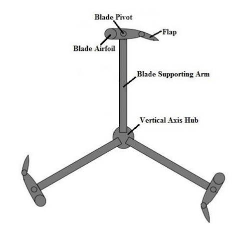
Top view of a VAWT system with both pitch and camber controls. Image by J. Ma, C. Koutsougeras, and H. Luo and taken from their COMSOL Conference 2016 Boston presentation.
From this system, the researchers modeled a 2D NACA 0012 airfoil within a rectangular area that represents one section of a wind tunnel. To simulate rotation, the rectangular box is moved while the airfoil is fixed in the horizontal direction.

Left: A NACA 0012 airfoil inside a rectangular wind tunnel. Right: The rectangular box is rotated to simulate an airfoil rotated 30°. The mesh seen here is used for illustration purposes. Images by J. Ma, C. Koutsougeras, and H. Luo and taken from their COMSOL Conference 2016 Boston paper.
The researchers used this model to analyze velocity and pressure at different airfoil pivot angles (wind angles of attack), support arm angles, and wind speeds. Through this, they can determine an optimal pivot angle for any given support arm position, maximizing torque and energy production and achieving a higher efficiency than VAWTs with fixed airfoils.
It’s important to note that this analysis does not include the centrifugal and Coriolis forces found in a VAWT system. As such, this study may be a good start, but the team needs to account for the influence of inertial forces for accurate and proper optimization.
Examining the Simulation Results in COMSOL Multiphysics®
The research team studied their model’s velocity profile at a 30° angle of attack when exposed to a wind speed of 20 m/s. They found the maximum air flow speed (35.6 m/s) near the leading edge of the airfoil and the minimum air flow speed (0.02 m/s) at the leading edge on the bottom side of the airfoil. This air flow behavior is mirrored when studying different airfoil rotation angles.

Left: The velocity field at a 30° angle of attack. Right: The velocity on the top and bottom airfoil surfaces. Images by J. Ma, C. Koutsougeras, and H. Luo and taken from their COMSOL Conference 2016 Boston presentation.
When looking at the pressure field of the airfoil surface at the same 30° angle of attack, the team noted that the peak pressure occurs in areas with the lowest flow speeds (close to the leading edge at the top of the airfoil) and vice versa. At the bottom of the airfoil, velocity and pressure remain almost constant except for the change near the leading edge.

Left: The pressure field at a 30° angle of attack. Right: The pressure on the top and bottom airfoil surfaces. Images by J. Ma, C. Koutsougeras, and H. Luo and taken from their COMSOL Conference 2016 Boston presentation.
Moving on, let’s examine the results for torque. Here, the researchers calculated torque in relation to the VAWT’s rotation center from the pressure field on the airfoil surface. As we can see in the following plot, torque increases with the angle of attack until it reaches its peak value at a 90° angle of attack. After this, torque drops and eventually returns to near-initial values as the angle of attack continues to grow.
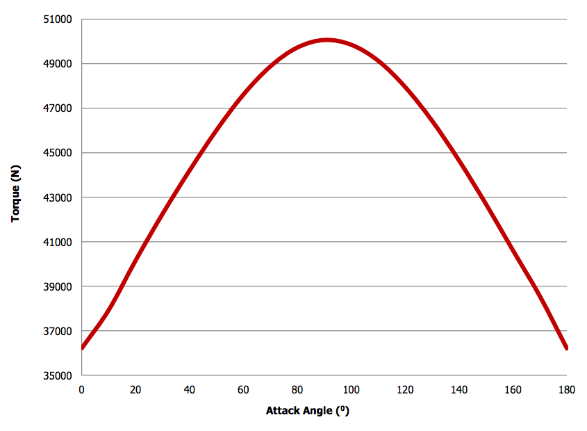
The torque with a support arm angle of 30° and wind speed of 20 m/s. Image by J. Ma, C. Koutsougeras, and H. Luo and taken from their COMSOL Conference 2016 Boston presentation.
Next, let’s see how torque values are affected by other support arm angles. The following results indicate that torque peaks at a 90° angle of attack for all support arm angles. As such, designing a control mechanism that keeps NACA 0012 airfoils at a constant 90° angle of attack will maximize device efficiency and energy production.


Comparisons of the torque distribution and attack angles for various support arm angles. The different curves represent support arm angles ranging from 0° to 90° (left) and 90° to 180° (right) at 10° increments. Images by J. Ma, C. Koutsougeras, and H. Luo and taken from their COMSOL Conference 2016 Boston paper.
In regards to laminar and turbulent wind speeds, when the support arm is constantly at 30°, there is an insignificant gain in torque due to the increased wind speed. Further, wind speed does not affect the torque distribution pattern.
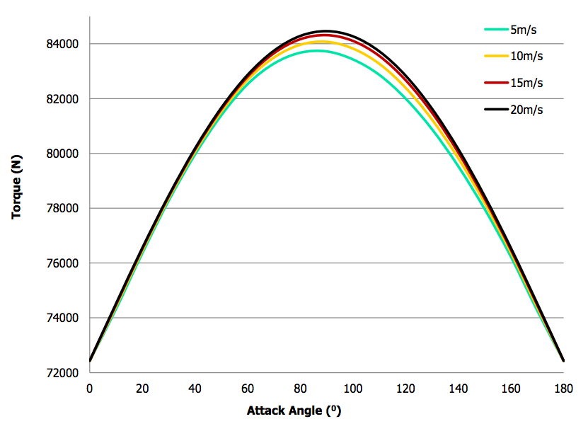
Comparison of the effects of different wind speeds. Image by J. Ma, C. Koutsougeras, and H. Luo and taken from their COMSOL Conference 2016 Boston presentation.
Designing Optimized Airfoil Pitch Control Systems for VAWTs
Using the knowledge gained from these studies, the researchers found that there is an optimal airfoil pivot angle that yields maximum torque at a given VAWT rotation angle. This information provides guidance for designing airfoil pitch control systems. For their next step, the team can increase the accuracy of their optimization by including centrifugal and Coriolis forces. Like we mentioned before, this is an important step in improving the study.
The researchers also hope to improve their studies by accounting for other factors, including multiple airfoils and support arms as well as the effect of wake from wind passing through one airfoil to another. In future studies, they are considering using a 2D and 3D multiblade model, studying a nonsymmetric airfoil, and more.
Learn More About Wind Turbines
- Read the full paper: “Efficiency of a Vertical Axis Wind Turbine (VAWT) with Airfoil Pitch Control“
- Browse the COMSOL Blog for more research on wind turbines:


Comments (0)