Exposure to the environment can negatively impact an antenna’s radiation characteristics and lead to greater losses. One way to protect these devices is with radomes, which are enclosures that can shield antennas while improving their overall performance. When designing a radome, measuring its effectiveness is key, as designs without optimized configurations have less influence. With the example of a patch antenna, we discuss using simulation to gain insight into a radome’s ability to improve antenna directivity.
Radomes Give Antennas an Added Layer of Protection
Powerful storms, strong winds, and heavy rain — we’ve all experienced the impact of harsh weather conditions. The strength of these forces can cause damage to surrounding structures and interfere with the operation of devices. In antennas, for example, such conditions affect how signals are transmitted and received.
To protect antennas from these conditions and other environmental factors, enclosures known as radomes — a name that comes from the combination of “radar” and “dome” — can be placed around them. With a nearly full transparency to radar waves, radomes help to minimize the loss of electromagnetic signals transmitted or received by an antenna while improving radiation characteristics such as antenna directivity. Further, the hardshell shape of the enclosure features strong properties that ward off damage to the antenna’s surface.
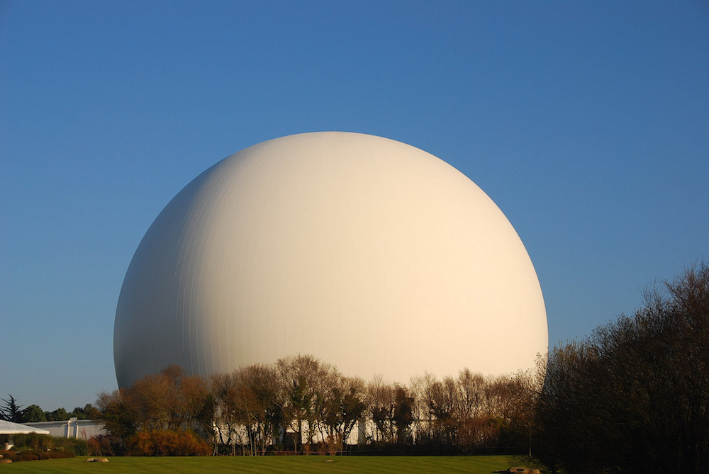
An example of a radome. Image by Nicolas Lannuzel. Licensed under CC BY-SA 2.0, via Flickr Creative Commons.
In order to optimize antenna directivity, it’s important to first measure the effectiveness of the radome design. With the COMSOL Multiphysics® software, we have access to features and functionality that enable us to do just that. To illustrate this, let’s look at the example of a patch antenna, which is popular in modern wireless devices.
Measuring the Effectiveness of a Radome Design in Improving Antenna Directivity
To represent the patch antenna model, we use a thin layer of metal, placing it on a circular dielectric over the ground plane. Both the antenna and ground plane are treated as infinitely thin perfect electric conductor (PEC) surfaces. A 50-Ω lumped port represents a feed from a power source to the antenna and a cylindrical polytetrafluoroethylene (PTFE) shell surrounds the entire structure.
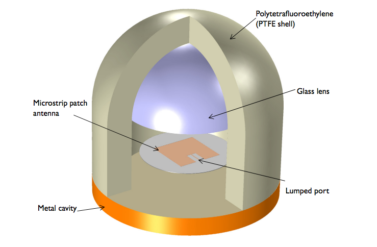
The radome and antenna structure.
We can increase the antenna gain by including a half sphere of quartz glass dielectric within the enclosure. Note that the structure as a whole is designed to operate at 1.632 GHz.
Let’s now turn our attention to the results. We can first look at the far-field radiation pattern in the model at 1.632 GHz. As shown below, the radiation pattern with the radome is more directive than that of a single patch antenna.
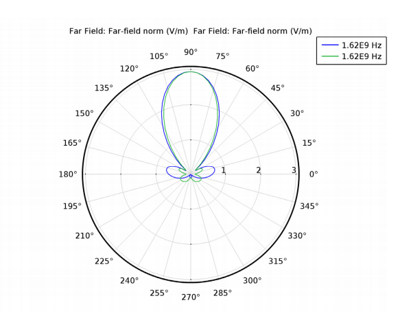
The far-field radiation pattern, with blue representing the E-plane and green representing the H-plane.
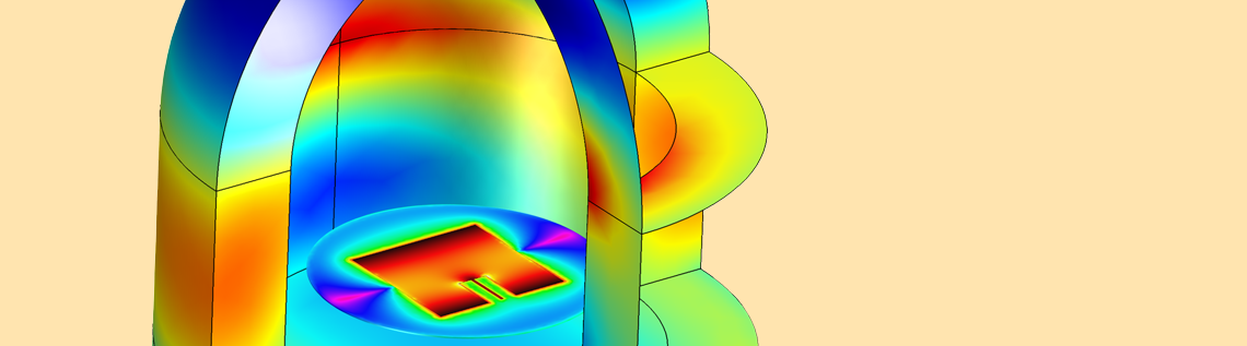
We can also visualize the electric field distribution on the radome shell, seen in the image below. The simulation results show that the electric fields are confined through the radome, which in turn produces stronger fields near the center of the top shell. The animation below illustrates how this electric field distribution evolves over phase variation.
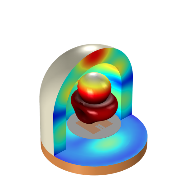
Distribution of the electric field in the radome shell (left) as well as its evolution over phase variation (right).
In this example, the radome design is a viable option for effectively improving an antenna’s directivity. With the flexibility of COMSOL Multiphysics, we can test the potential of a radome design, achieving the optimal configuration for a specific application.
Learn About Designing Antennas with COMSOL Multiphysics®
- Looking for an introduction to modeling antennas? Here’s a blog post you’ll want to read: Introduction to Efficiently Modeling Antennas in COMSOL Multiphysics®
- Try other antenna tutorial models from our Application Gallery:


Comments (0)