Stress Analysis of a Pipe Fitting from a CAD File
Application ID: 102831
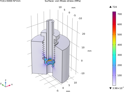
This tutorial model shows the setup of a 2D axisymmetric stress analysis, through contact, of a 3D threaded pipe fitting.
The example involves synchronizing the 3D PTC Creo Parametric™ geometry and selections, which specify the faces in contact, with the 2D geometry in COMSOL Multiphysics®. A cutting plane is defined in COMSOL Multiphysics® to create the 2D geometry from the synchronized 3D objects. The model setup is simplified by using the synchronized selections that are available on the 2D geometry.
This model example illustrates applications of this type that would nominally be built using the following products:
however, additional products may be required to completely define and model it. Furthermore, this example may also be defined and modeled using components from the following product combinations:
- COMSOL Multiphysics® and
- LiveLink™ for PTC Creo Parametric™ and
- either the MEMS Module, Multibody Dynamics Module, or Structural Mechanics Module and
- either the Acoustics Module, MEMS Module, Metal Processing Module, or Structural Mechanics Module
The combination of COMSOL® products required to model your application depends on several factors and may include boundary conditions, material properties, physics interfaces, and part libraries. Particular functionality may be common to several products. To determine the right combination of products for your modeling needs, review the Tabella delle Funzionalità and make use of a free evaluation license. The COMSOL Sales and Support teams are available for answering any questions you may have regarding this.