
The 5G mobile network and Internet of Things (IoT) are two hot topics in the RF and microwave industry. New developments in these wireless applications call for much higher data rates, active electronically scanned arrays (AESA), phased array antennas, and multiple-input-multiple-output (MIMO) technology. It is important to reduce the time and cost during the process of prototyping and manufacturing these applications. Using simulation and apps, we can streamline the development cycle of wireless communication designs.
Advanced Computational Resources for 5G Phased Array Antenna Designs
As we discussed in a previous blog post, there are many required advancements and design considerations for the 5G mobile network. One of the improvements that RF engineers need to work toward is increasing antenna gain to serve the much higher frequencies on which 5G will operate.
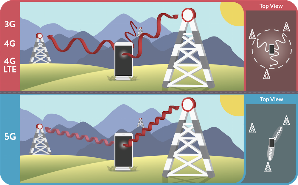
An isotropic low-gain antenna used in older networks versus a directive high-gain antenna used for 5G.
Another requirement of the 5G mobile network is that we improve phase progression technology. This shapes the radiation pattern and steers the beam of an antenna array to control the input signal and address angular coverage issues.
A monopole phased antenna array can steer a beam toward the desired direction.
One device, a slot-coupled microstrip patch antenna array, can be incorporated into designs to address these coverage issues. However, there are many complex design parameters that must be considered in order to build a device that is optimized for 5G wireless communications.
Simulation can help by offering the capability to evaluate and implement physical effects that can not be easily tested in a design lab or through prototyping, such as extreme temperature variation, structural deformation, and chemical reactions. Unfortunately, not every engineer working on a design may be an expert in simulation, requiring the simulation expert on the team to be involved in every step of the design process whenever there are new changes to an antenna array design or simulation environment.
The Application Builder addresses these difficulties by further enhancing the capabilities of simulation. Now, an otherwise complex and tedious numerical model of an RF design can be turned into an interactive and user-friendly tool for experts and end users alike. Today, let’s explore the Slot-Coupled Microstrip Patch Antenna Array Synthesizer simulation app and how it can help us optimize phased array antenna designs for 5G and IoT.
Using the Slot-Coupled Microstrip Patch Antenna Array Synthesizer App
Active electronically scanned arrays (AESA), also known as phased antenna arrays, are conventionally used in the military for radar and satellite applications. These arrays are also used in a new application — commercial purposes — due to the growing needs of higher data rates in communication devices. The size of this simple component can easily exceed tens of a wavelength, causing simulation design to be very memory intensive. As a result, computation takes a very long time, even when only approximated values are needed to evaluate a proof-of-concept model. Faster prototyping would help to analyze performance and determine design parameters quickly.
The Slot-Coupled Microstrip Patch Antenna Array Synthesizer is based on a full finite element method (FEM) model of a single microstrip patch antenna built on low-temperature cofired ceramic (LTCC) layers. The device initially operates at 30 GHz, and the radiation pattern and directivity analysis of the entire array structure are integrated using the very powerful postprocessing functionality of COMSOL Multiphysics. The Application Builder works as a shortcut to provide a variety of ways to design and build the user-friendly graphical user interface (GUI), transforming an ordinary mathematical model into an intuitive simulation tool.
The top view of a slot-coupled mictrostrip patch antenna.
The Application Builder offers two essential tools for creating our app: the Form Editor and Method Editor. The Form Editor enables us to design the GUI with simple functionality by adding form objects to a custom interface. The Method Editor helps to implement more advanced and customized functions over the form objects. After an accurate simulation of a single microstrip patch antenna, we find the two-dimensional antenna array factor
This corresponds to user input, such as array size; arithmetic phase progression; and angular resolution, which is imposed on the single antenna radiation pattern data (emw.normEfar).
The Method Editor moves beyond a simple simulation, where visualization is limited to the predefined postprocessing variables, and allows for further customization.
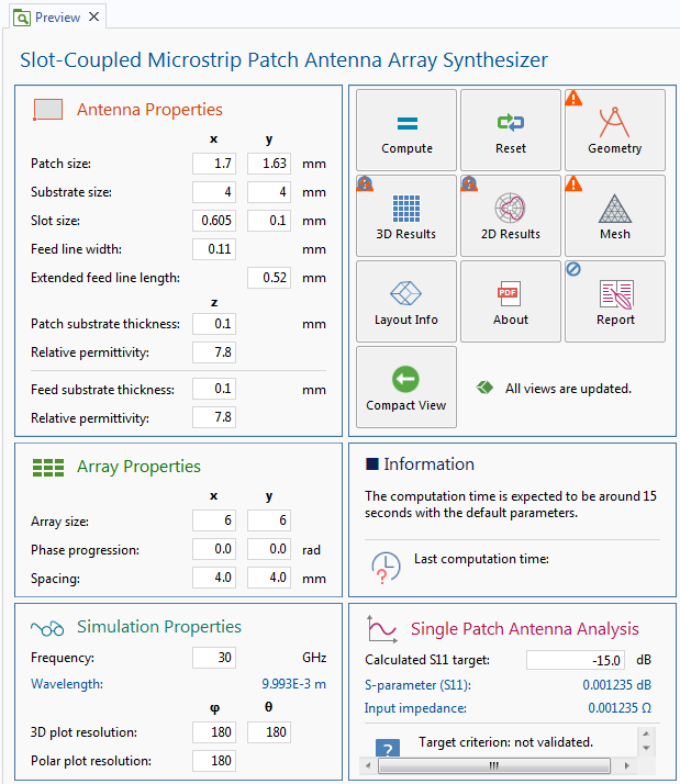
A preview of the main form to show form objects.
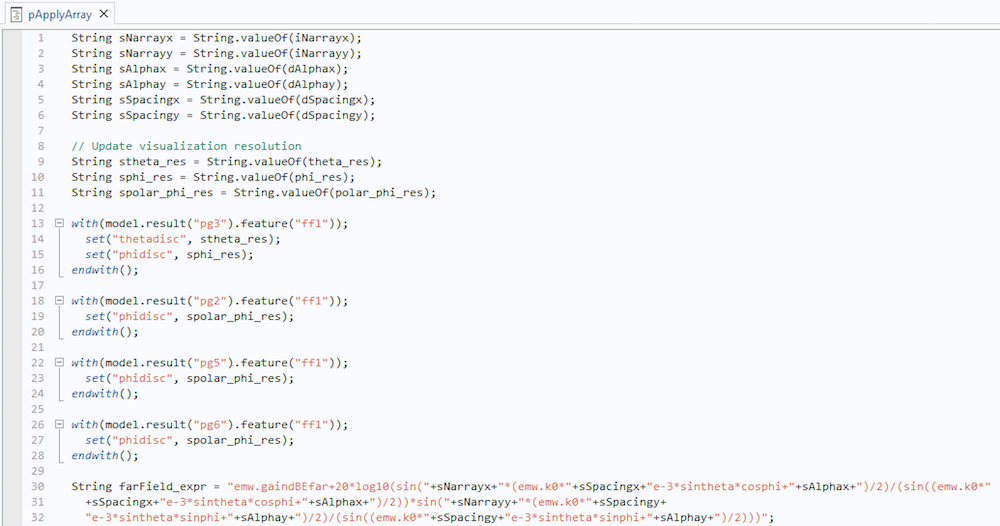
Using the Method Editor to create custom actions for form objects.
In this app, there are many design parameters that we can test for our microstrip patch antenna array design, including:
- Antenna properties
- Patch size
- Substrate size
- Slot size
- Feed line width
- Extended feed line length
- Patch substrate thickness and relative permittivity
- Feed substrate thickness and relative permittivity
- Array properties
- Array size
- Phase progression
- Spacing
- Simulation properties
- Frequency
- Wavelength
- 3D plot resolution
- Polar plot resolution
The array dimension, phase progression and spacing, and the distance between each element primarily characterize the shape and direction of the array antenna radiation pattern. The angular resolution also adds a delicate touch on the 3D and 2D radiation pattern visualization. Note that when the antenna directivity is higher, using a finer resolution will more accurately describe the sidelobes.
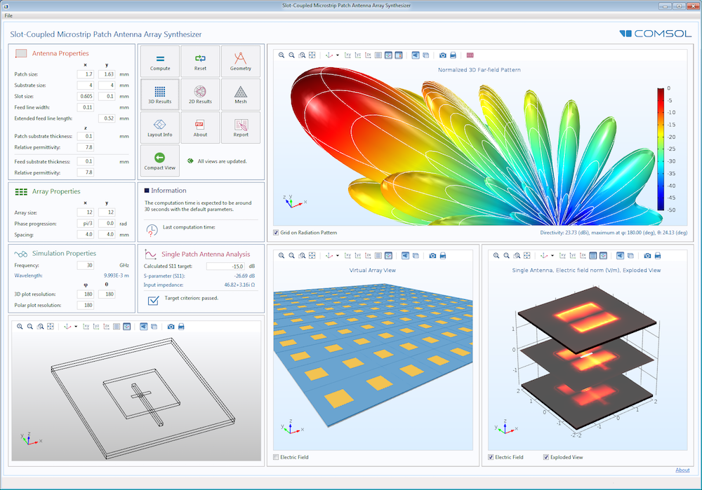
The GUI of the Slot-Coupled Microstrip Patch Antenna Array Synthesizer app.
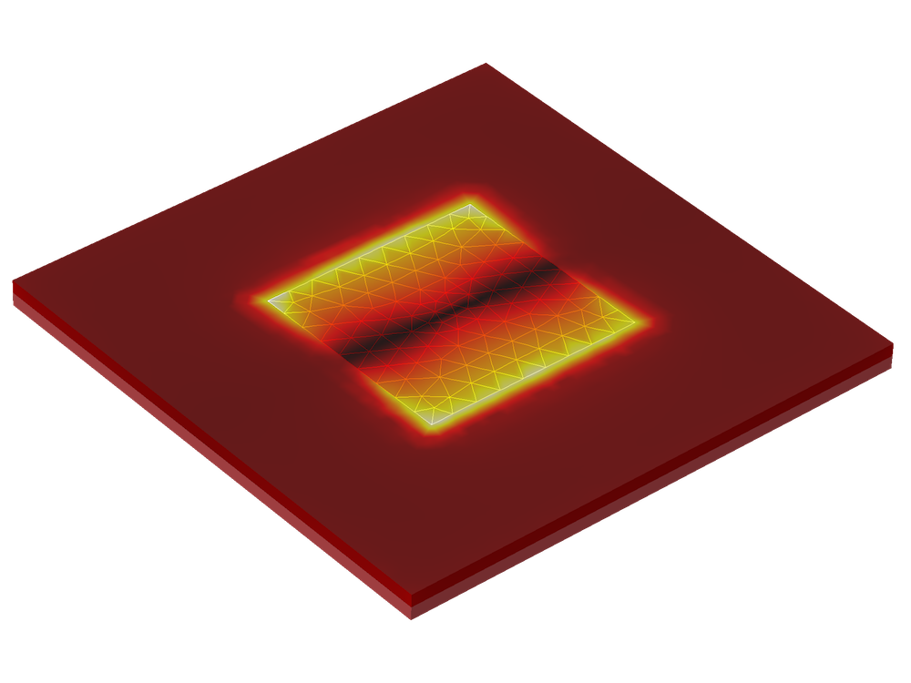
After the analysis, the app reports whether the single antenna design parameters are optimal by using the computed S-parameter (S11) value compared to the pass/fail target criterion that the app user specifies before running the simulation. The app depicts the electric field distribution on each dielectric and metallic layer and also visualizes the entire view of the array to give app users a better feel for the performance of the design. You can also choose to include a complete simulation result report and documentation that concisely explains how the app works.
Simulation Apps Provide Unlimited Ways to Present a Numerical Model
There are infinite ways to convert your model into a customized tool by using the Application Builder, but what’s next? You can launch and use your simulation app with the core COMSOL Multiphysics® software. As long as you have an internet connection, you can run your app using a common web browser and even deploy it to colleagues and customers via COMSOL Server™ product.
In the Application Gallery, even more apps are available for you to download and explore, covering physics areas such as electrical, mechanical, fluid, chemical, and more. These demo apps can serve as a guide for you to build useful apps of your own.


The Frequency Selective Surface Simulator demo app (left) and the Plasmonic Wire Grating Simulator demo app (right).
Whether you are building an app to enhance RF designs for the 5G network, or working in another application area, get started building simulation apps and optimizing your design workflow and product performance today.
Further Reading
- Try it yourself: Download the Slot-Coupled Microstrip Patch Antenna Array Synthesizer
- Read more about RF design applications for 5G and the Internet of Things on the COMSOL Blog:
- Watch a video to learn how to start building simulation apps from your own models


Comments (0)