
Ocean acoustic tomography systems measure temperature using an acoustic signal that travels between two instruments. These systems often need to cover a broad frequency band with low-frequency signals and require a high-power sound source. One option to achieve these goals is a tunable organ pipe, which balances efficiency and functionality. A researcher at the Advanced Technology Group, Teledyne Marine Systems used simulation to improve his tunable organ pipe design and compared the results to experimental tests.
Taking a Closer Look at Ocean Acoustic Tomography
Saying that the world’s oceans are large is an understatement. Oceans cover around 71% of Earth’s surface and the deepest known point, the Challenger Deep in the Mariana Trench, extends down for about 36,000 feet (almost 11 km). To study this massive environment, researchers need powerful, far-reaching tools.

The depth of the Challenger Deep compared to the size of Mount Everest. Image by Nomi887 — Own work. Licensed under CC BY-SA 3.0, via Wikimedia Commons.
Ocean acoustic tomography, which involves deep-water, low-frequency sound sources, is one option for measuring the temperature of oceans. This system measures the time it takes sound signals to travel between two instruments at known locations, a sound source and a receiver. Because sound travels faster in warmer water, you can use this measurement to extract the average temperature over the distance between the source and the receiver.
To get these measurements, long-range ocean acoustic tomography must be able to use low-frequency signals to cover a broad frequency band, something that often requires a high-power sound source. Therefore, creating a system that can successfully cover a large frequency band, while reducing power consumption via a highly efficient design, is ideal. One particular focus in this field is on resonators, since saving energy in a resonator helps increase overall transducer efficiency in cases where the wavelength is larger than its dimension.
In response to this, Andrey K. Morozov at Teledyne Webb Research (TWR) developed a sound resonator design that is highly efficient and has a tunable resonator. While previous research involved a high-Q resonant organ pipe operating at a frequency band of 200-300 Hz, this study revolves around a new high-frequency sound source that operates at an octave band of 500-1000 Hz. Further, the new high-Q resonant organ pipe design can keep a system in resonance when the transmitted signal has a changing instantaneous frequency. With its small size, this design is helpful for shallow water experiments.
In this design, a digitally synthesized frequency sweep signal is transmitted by a sound projector. The projector and high-Q resonator tune the organ pipe so that it matches a reference signal’s frequency and phase. This resonant tube can operate at any depth, but before it was ready to hit the seas, Morozov studied its design using the COMSOL Multiphysics® software.
Predicting Optimal Parameters in an Organ Pipe
As we can see in the schematic below, the organ pipe device is comprised of slotted resonator tubes (or pipes) that are moved via a symmetrical Tonpilz transducer. The Tonpilz driver’s piezoceramic stacks move pistons and thereby vary the volume. The two symmetrical pipes that are coupled through the Tonpilz transducer function like a half-wave resonator that has a volume velocity source driver.
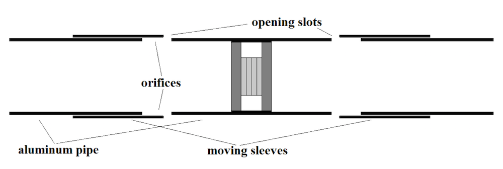
Image of a tunable resonant sound source and Tonpilz driver. Image by Andrey K. Morozov and taken from his COMSOL Conference 2016 Boston paper.
Let’s focus on how these resonator tubes include slots or vents. In order to achieve smooth control of the resonance frequency, an electromechanical actuator moves two sleeves axially along the resonator tubes, maintaining a small gap in between the sleeve and pipe. Through this action, the slots are covered and the actuator can tune the organ pipe in a large frequency range. When the sleeves’ positions relative to the slot change, the equivalent acoustic impedance of the slots also changes, altering the resonance frequency of the entire resonator.
In the next section, we’ll see how simulation was used to further improve the design of the tunable organ pipe.
Using Acoustic Simulation to Analyze Tunable Resonator Acoustics
Morozov reduced the thickness of the resonator’s walls to make them lighter, which caused them to vibrate and store a large amount of acoustical energy. To prevent acoustical coupling between the main resonator and a mechanical part of the system, he used shock mounts to attach the main resonator pipe to the backbone rail. This design change did not completely avoid unwanted resonance effects in the tuning mechanics, so Morozov turned to simulation for further optimization.
The plot below and to the left represents the sound pressure level at resonance. Here, the vents in the main resonator pipe open and sound energy leaves the organ pipe through the resulting gap. In a low-frequency design, rounded edges in the sleeve cylinder help to prevent dual resonances in this position, but this isn’t a complete solution for a high-frequency resonator.
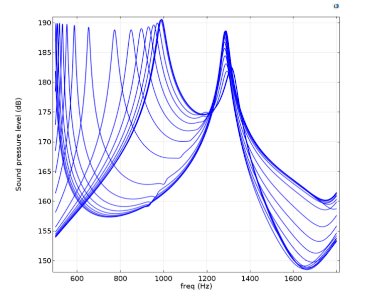
To learn more, the researcher studied the resonance curves for different sleeve positions, as seen below and to the right, shifting each position in 1 cm intervals.


Left: Simulation results of a tunable organ pipe, performed for a standard spherical driver. Right: Results showing the different sleeve positions and their correlating frequency responses. Image by Andrey K. Morozov and taken from his COMSOL Conference 2016 Boston paper.
His results showed that the vibrations in the main pipe and the resonating water beneath the sleeve can disturb the main resonance curve. Although both simulation results and experimental tests agree that this problem can be alleviated by increasing wall thickness, the resulting pipe design is too heavy.
To address this issue, Morozov easily tested different design configurations with simulation. He discovered that the tunable mechanism can be improved by ensuring that the gap between the sleeve and the main pipe is only from one of the orifice’s sides. Using this improved design as a basis, he completed additional studies, including investigating the optimal frequency, particle velocity, and sound pressure of the device, which we’ll focus on next.
Comparing sound pressure levels and frequency in the improved design for various sleeve positions. Image by Andrey K. Morozov and taken from his COMSOL Conference 2016 Boston paper.
In this new design, the pipe first functions as a half-wavelength resonator and radiates through its main orifices. At the end of the frequency band, the sound is mostly radiated through the completely open tuning vents, as seen in the following images. The transition between these two states is continuous.


Absolute sound pressure when the slots are completely closed at the starting frequency range of 500 Hz (left) and when the slots are completely open at the maximum resonance frequency of 1000 Hz (right). Images by Andrey K. Morozov and taken from his COMSOL Conference 2016 Boston paper.
To conclude, these simulations enabled Morozov to successfully visualize the structural acoustics of a new high-Q resonant organ pipe with an octal band of 500 to 1000 Hz and investigate important details, including the optimal profile of the opening slots.
Comparing Simulation Results to Physical Experiments
Finally, a physical organ pipe was constructed out of aluminum using the exact dimensions of the model. The initial test pool results were similar to the simulation results and achieved the expected frequency range. However, the resonance frequencies were slightly lower in these tests. This is likely explained by the elliptical shape of the pipe and the limited pool dimensions. Both factors contributed to the decreased resonance frequency.
Due to these results, Morozov altered his experiment by cutting the pipes, as well as by performing another test at the Woods Hole Oceanographic Institution dock.
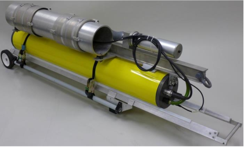
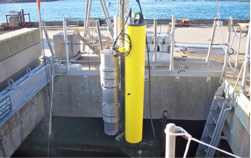
The altered sound source system (left), tested at the Woods Hole Oceanographic Institution (right). Images by Andrey K. Morozov and taken from his COMSOL Conference 2016 Boston paper.
The new experiment indicated that while the simulation could efficiently predict resonance frequencies, the model’s Q-factor is larger than in the experimental results. This difference is expected because real losses are hard to predict. Also, there were slight variations between the model and the realized design.
Designing a tunable resonant system is challenging because you need to precisely adjust parameters and ensure that it achieves the necessary frequency range. Using COMSOL Multiphysics, Morozov managed to achieve the octave frequency range in his tunable sound source design before performing a large amount of water tests. He found that the physical sound source parameters reasonably matched the simulation.
This improved design can help scientists measure long-range sound propagation and temperature over large distances in the ocean, allowing them to study everything from small-scale temperature fluctuations to overarching oceanic climate change.
Learn More About Simulation Research and Organ Pipes
- Download the original paper: “Simulation and Test of Tunable Organ Pipe For Ocean Acoustic Tomography“
- Head this way for an overview of the top papers and posters from the COMSOL Conference 2016 Boston
- Learn more about organ pipe design in this blog post: Hear the Sound of an Organ Pipe Design with a Simulation App


Comments (0)