

A key stage during the manufacturing process of polymer composite materials, such as carbon fiber, is the infiltration of a polymer resin with a fibrous and porous (permeable) reinforcement material. Traditionally, the permeability is measured from experiments, which can be expensive and time consuming to perform. In this blog post, we explain how the COMSOL Multiphysics® software can be used to quickly and accurately model the permeability constant of an idealized composite reinforcement material in order to successfully improve product quality.
Polymer Composite Materials
Polymer composite materials, such as carbon-fiber-reinforced polymer (CFRP), are used extensively in the aerospace, automotive, and wind turbine industries due to their high performance and low weight — enabling significant reductions in fuel and energy consumption. In the case of CFRP, the composite material consists of a combination of two materials:
- Fibrous structural reinforcement material (e.g., carbon fiber), which primarily provides strength in tension
- Polymer resin (e.g., epoxy), which helps to transfer loads across fibers while providing strength in compression

An image of a BMW i3® plug-in hybrid concept car cutaway, showing the carbon fiber structure and the electric motor. Image licensed under CC BY-SA 3.0, via Wikimedia Commons.
The structure of the reinforcement material often consists of individual fibers with a diameter of approximately 10 µm formed into bundles of thousands of fibers called tows, before being arranged into reinforcement fabrics, e.g., unidirectional or woven on the length scale of the component to be manufactured.
The polymer composite material is formed during manufacture using processes such as resin transfer molding (RTM), which involves the infiltration of the viscous polymer resin through the porous (permeable) reinforcement material before resin cure. During this stage, the flow of the resin can occur on a macroscale (length scale of the component) and a microscale (length scale of the fiber), where the flow can be both intra- and intertow.
Understanding the permeability of the reinforcement material is important as it can help to:
- Improve the accuracy of simulations modeling the mold filling (infiltration) stage
- Optimize process parameters such as injection pressure
- Improve final product quality by reducing defects such as uninfiltrated regions, dry spots, fiber displacement, intra- and intertow void formation, and uneven filtration called race-tracking
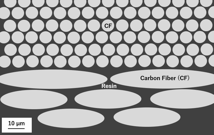
A cross section image showing the typical structure, distribution, and size of carbon fibers in resin.
The Role of Clean Water and Henry Darcy
In 1856, while working to improve the quality of water in Dijon, France, hydraulic engineer Henry Darcy published “The Public Fountains of the City of Dijon”, in which he outlined an equation that describes the saturated laminar flow of a Newtonian fluid through a homogenous porous medium on a macroscale. This equation, called Darcy’s law, found use in hydrology worldwide and has since been applied to the simulation of the mold filling stage of RTM. Darcy’s law is defined as follows:
where \mathbf v is the superficial velocity (observed on a macroscale), \mu is the dynamic viscosity, \mathbf K is the permeability of the fabric, and P is the pressure (angled brackets denote volume averaging).
The permeability \mathbf K is a tensor quantity with units of area and indicates the ease with which a fluid will flow through a porous media.
Modeling the Permeability of an Idealized Composite Reinforcement Material
Let’s model the transverse nondimensional permeability of an idealized unidirectional composite reinforcement material by representing the tow as a solid (impermeable) circular cylinder arranged in a square periodic array. This approach will allow us to validate the COMSOL Multiphysics simulation results by comparing directly to published analytical theory and the results of experiments.
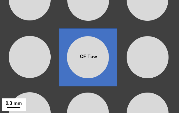
A cross section image showing an idealized composite reinforcement material with carbon fiber tows in a square periodic array with a blue domain representing a repeating unit cell.
Theory
We can obtain a solution for the flow transverse to a square periodic array of circular cylinders by solving the stationary form of the Navier–Stokes equations in a unit cell domain (blue area in the image above) surrounding a cylinder. It should be noted that for very low Reynolds number flow, \mathbf Re\ll1, we can also obtain a solution in COMSOL Multiphysics by solving the Stokes or creeping flow equations.
Model Overview
The setup of the unit cell model and the application of the boundary conditions are as follows. A unit pressure drop is applied from the left-hand boundary to the right-hand boundary using the Periodic Flow condition in conjunction with a pressure point constraint. A Symmetry condition is then applied to the top and bottom boundaries and a Wall condition with no slip is applied to the boundary of the cylinder. The density \rho and dynamic viscosity \mu of the fluid are defined with a unit value.
As we are interested in calculating the nondimensional permeability for a range of cylinder area fractions a\scriptstyle f from 0.05 to 0.7, we can parameterize the geometry and perform a parametric sweep for all values in one computation. The mesh is defined as physics controlled with an extremely fine element size, allowing us to resolve the high velocity gradients between adjacent cylinders when the cylinder area fraction is high and the cylinders are nearly touching one another.
The permeability is nondimensionalized with respect to the length scale of the cylinder radius and then calculated from the following equation:
which includes the inverse of the drag coefficient Cd=\frac{F}{\mu \overline{\mbox{u}}}, where F is the product of the pressure drop and the cross-sectional area measured normal to the direction of the pressure drop.
Results
The simulation results are shown in the figures below. The pressure and velocity gradients are highest in the region near the adjacent cylinders, where the fluid flow gap is smallest.


Simulation results showing pressure contours (left) and velocity contours (right) for flow transverse to a square periodic array of cylinders at a solid area fraction of a\scriptstyle f=0.7.
The results of the nondimensional permeability K_{non} are compared to the published theory and experiments based on solid cylindrical rods showing excellent agreement for a wide range of solid area fraction a\scriptstyle f, indicating a nonlinear decrease in permeability with increasing a\scriptstyle f.
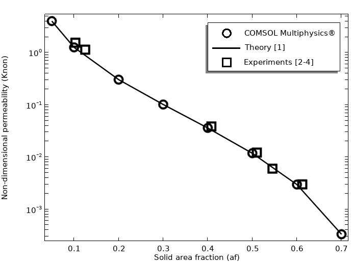
Simulation results showing the nondimensional permeability compared with the results of theory and experiments for flow transverse to a square periodic array of cylinders.
Closing Remarks
In this blog post, we have shown how COMSOL Multiphysics can be used to quickly and accurately model the permeability of an idealized composite reinforcement material. The simulation results were validated by comparison with published theory and experiments showing excellent agreement. The current model provides a stepping stone to analyzing parallel flow and the permeability of more complex tow shapes that include intratow permeability, allowing the development of more accurate simulations for the manufacture and optimization of composite materials.
In addition to modeling the permeability of composite reinforcement materials, COMSOL Multiphysics can be used for measuring the permeability for a wide range of other porous materials.
Next Steps
- Try this related tutorial model:
- Check out these related blog posts:
References
- A.S. Sangani, and A. Acrivos, “Slow flow past periodic arrays of cylinders with application to heat transfer”, International Journal of Multiphase Flow, vol. 8, no. 3, pp. 193–206, 1982.
- L. Skartsis, B. Khomami, and J.L. Kardos, “Resin flow through fiber beds during composite manufacturing processes. Part II: Numerical and experimental studies of Newtonian flow through ideal and actual fiber beds”, Polymer Engineering and Science, vol. 32, no. 4, pp. 231–239, 1992.
- T.A.K. Sadiq, S.G. Advani, and R.S. Parnas, “Experimental investigation of transverse flow through aligned cylinders”, International Journal of Multiphase Flow, vol. 21, no. 5, pp. 755–774, 1995.
- A.A. Kirsch and N.A. Fuchs, “Studies on fibrous aerosol filters-II. Pressure drops in systems of parallel cylinders”, Annals of Occupational Hygiene, vol. 10, pp. 22–30, 1967.
- S. McCallum, “Experimental, Analytical and Computational Studies in Resin Transfer Moulding”, in Department of Materials. 2003 Thesis (PhD), Imperial College of Science Technology and Medicine, London, UK.
BMW i3 is a registered trademark of Bayerische Motoren Werke Aktiengesellschaft.

Comments (0)