
With the release of version 5.5 of the COMSOL Multiphysics® software, there is a feature for tracking the state, or history, of your model. The State Variable feature simplifies the tracking of the history of a field over time. These variables can also be used to affect other fields, such as material properties, and can thus be used to implement hysteresis into your model. Let’s look at this new functionality and see how to use it.
The State Variables Interface
The State Variables interface is available when you enable the Variable Utilities option within the Model Builder, as shown in the screenshot below.
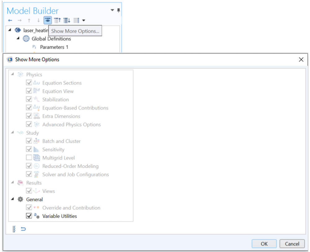
How to enable the Variable Utilities option.
Once the option is enabled, you’ll see a Variable Utilities button within the Definitions ribbon, and a Variable Utilities submenu when you right-click the Component > Definitions branch within the model tree. Once you’ve added this feature, you can define variables on any geometric entity level, including:
- Domains
- Boundaries
- Edges
- Points
The settings for this feature are shown in the screenshot below.
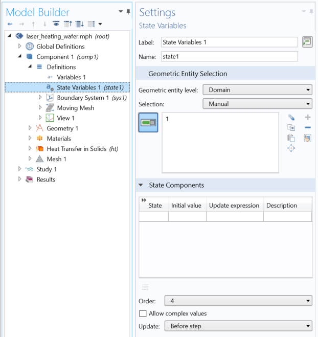
The State Variables settings.
There aren’t many settings here that we need to look at, but there is a lot we can do with this feature.
Let’s start from the setting at the bottom of the window. The state variable can be updated either before each time step (or parameter step) or after. If you expect complex-valued numbers, enable the Allow complex values option.
Next, the Order controls at how many points within each element the state variables are saved. This order corresponds to the Gauss-point data element order. An order of 0 would mean that, over each element, there is only a single state variable defined. The default order of 4 corresponds to the Gaussian integration points that are used by the quadratic element order used by most physics, but if you use different element orders, adjust this setting to be twice the order of the element.
Finally, the State Components settings allow you to define several state variables, their initial conditions, and how they should be updated.
Let’s next look at some examples of how to use this functionality.
Tracking the Maximum of a Field
Suppose that we have a transient model where the temperature is fluctuating in time. A good example of this is the Laser Heating of a Silicon Wafer example from the Application Gallery. We can track the maximum temperature that the part gets to by defining a state variable MaxT, with an initial value of 0 (or any value lower than or equal to the initial temperature field) and use this variable to store the maximum temperature via the update expression:
if(T>MaxT,T,MaxT)
This if statement evaluates to true whenever, and wherever in space, the temperature field, T, is greater than MaxT, and then MaxT will take on the value of the temperature. Otherwise, MaxT remains equal to its current value. In this case, we would want to update the variable after each step. So, just as the temperature field varies in space and time, the state variable will also.
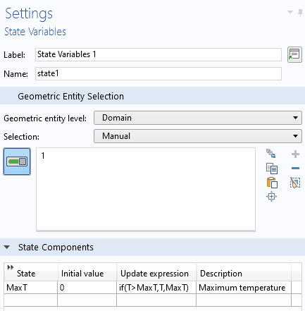
The definition of the state variable MaxT.
When plotting the MaxT field, keep in mind that these state variables do not keep track of units and that the data, which is stored at the Gauss points, is extrapolated and interpolated over the entire element, so this field can look slightly different from the temperature field, which is stored at the node points and plotted via interpolation. The plot below shows what our results will look like.
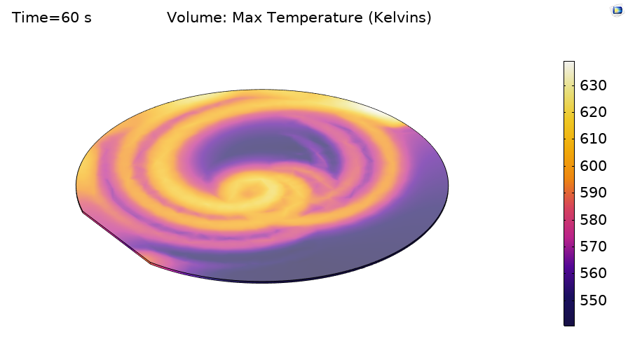
A plot of the state variable that tracks the peak temperature achieved over the entire simulation time span.
Using the State Variable to Affect the Physics
Next, let’s use the State Variable feature to affect the same laser heating model.
Suppose that our wafer has a thin coating on the top that strongly affects the surface emissivity. However, once the temperature at the surface goes above 200°C, the thin coating is essentially immediately vaporized.
Our laser heating model already defines a Global Parameter called emissivity, which is a constant value of 0.8 and is used within the model to define both the absorbed and radiated heat. We can remove this constant global definition and instead define a state variable over the top surface, of the same name, with an initial value of 0.8, and with the update expression of:
if(T>200[degC],0.2,emissivity)
This if statement triggers a permanent change to the state variable, emissivity, which is defined over the surface of the wafer and used by the Heat Flux and Surface-to-Ambient Radiation features. We would want to update this variable before each step.
Implementing a Hysteresis Model
Let’s finish up with the more complicated example of hysteresis.
We will stick with solving for a temperature field, a topic which we’ve already discussed in a previous blog post, Thermal Modeling of Phase-Change Materials with Hysteresis, where we show that thermal hysteresis can be modeled by using two different functions for specific heat as a function of temperature, depending upon if the material is transitioning from the solid to the liquid state, or liquid to solid. Once the material becomes fully liquid, or fully solid, we will want to switch the function used to define the material properties.
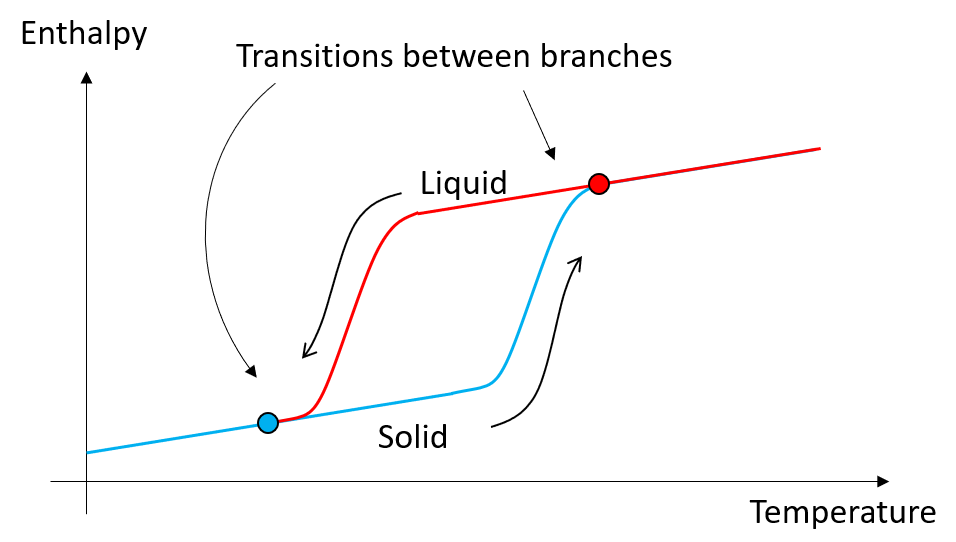
To implement such a model, we need to introduce a switching state variable to decide if we should be following the lower or the upper branch. This switch can be based upon if the temperature rises above, or falls below, the two marked transition temperatures. So, introduce a state variable, SorL, with initial value of 1 (presuming the material is initially solid) and with the update expression:
if((T>T_top),0,if(T<T_bot,1,SorL))
This nested if statement will switch the value of SorL to 0 if the temperature rises above the upper threshold, and only switch it back to 1 if the temperature drops back below the lower threshold. The material property can then be conditional upon the SorL state variable. For example, in this case, the heat capacity can be defined via an if statement as:
if(SorL,SolidtoLiquid(T),LiquidToSolid(T))
where SolidtoLiquid(T) and LiquidToSolid(T) are two different functions of temperature associated with the two different branches.
Closing Remarks
The State Variables functionality makes some of our modeling work a lot more convenient and easier to use. We encourage you to try it out and see what other applications you can come up with. Happy modeling!
Try It Yourself
Download two of the examples featured in this blog post by clicking the button below.


Comments (6)
Dirk Kähler
June 3, 2020What ist the difference between the new state variable and the old previous solution operator, you explained some years ago in a blog post (https://www.comsol.com/blogs/using-the-previous-solution-operator-in-transient-modeling)? In case the state variable is evaluated before the step what does COMSOL do? Is it a segregated approach?
Walter Frei
June 3, 2020 COMSOL EmployeeHello Dirk,
The new functionality is simply easier to use, as there are far less settings (and especially solver settings) to adjust. Functionally, though, it is equivalent.
Michael Rembe
June 22, 2020Hi Walter,
would you recommend to use a state domain variable as parameter? I run a very complex 3D model, one parameter is computed depending on a wall distance and another local dependency. I assume, that the parameter is recomputed every iteration step, but this is not necessary. The parameter should be computed only once at initialization. I use the domstate variable with he computed initial value and then domstate=domstate. Would you agree with this?
Best regards, Michael Rembe
Walter Frei
June 22, 2020 COMSOL EmployeeDear Michael,
That is an interesting question, but likely not one which can be addressed here. Please contact support@comsol.com and mention this, as we will address it.
Ivar KJELBERG
March 30, 2021Hello Walter,
Since some releases you have added quite some functionalities under “Variable Utilities” but I’m lacking good examples to ensure I understand them correctly and use them all at the best (this seems to be the only BLOG on one of eleven!) . Any chance you may give us a blog or a Video on how to use these other interesting new features ?
It looks like you are gently getting COMSOL to accept full tensor notations and have the GUI to fill in the details while we may write high level equations and not need to develop everything at component level …
Would be nice 🙂
Sincerely
Ivar
Songcai Han
August 21, 2021Hi Walter,
It works well for homogeneous materials. However, it is found that the solutions (such as stress and strain) at previous step cannot be accurately recorded for a model with heterogeneous material properties, no matter what Order you select. The same problem will appear if adopting the Previous Solution node. So how to solve this problem?
Thanks,
Songcai