
The COMSOL Multiphysics® software provides easy ways of modeling chain drive systems. In the first part of this chain drive modeling blog series, you will see how to create realistic geometry models of roller chain sprocket assemblies using the built-in parametric geometry parts in the COMSOL Multiphysics Part Library.
Introduction to Chain Drive Systems
You know how essential a chain on a bicycle is. When you push the pedals and rotate the front sprocket of a bicycle, it is the chain that transmits this rotation to the rear sprocket and its connected wheel. Similar assemblies of chains and sprockets are also used in many machines to transfer power from one shaft to another or lift heavy objects.
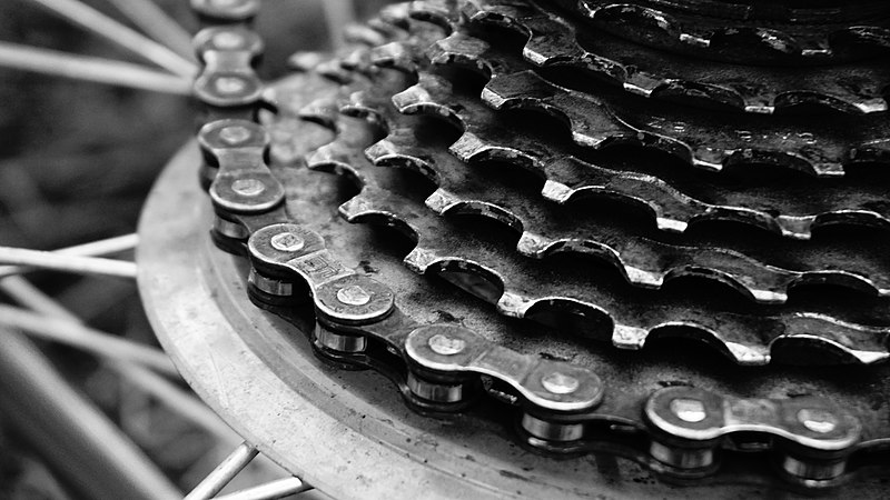
The chain drive and gears of a bicycle. Image by 5 Cent Dollar — Own work. Licensed under CC BY-SA 4.0, via Wikimedia Commons.
Chain drives are an important class of power transmission systems, widely used in many industrial applications. Their main uses include transferring torque or motion, conveying material, or synchronizing motion between different components of a mechanical assembly. Chain drives made of different materials and varying sizes are used in a wide variety of applications, such as automobiles, conveyors, and hoisting devices like forklifts.
The two basic components of a chain drive system are a chain and sprockets. The chain is an assembly of links, joined using pin connections. It is wrapped around one or more toothed wheels, known as sprockets, that are generally mounted on specified shafts in a machine. The chain transfers motion from one sprocket to another by meshing and sliding over the teeth of the contacting sprocket.
Depending on their use, the chain and sprocket in a chain drive can be of different types. While silent chains, leaf chains, and flat top chains are some of the available chain types, the most commonly used type for power transmission is the roller chain. Similarly, there are a variety of styles of sprockets that are suited for specialized needs.
The choice of the right power transmission system for your application depends on many factors. While chain drives offer many advantages over gears and belt drives, they also lack certain merits of these alternatives. The slip and frictional loss observed in a belt drive is minimal in chain drives. Compared to belt drives, they are compact, easy to install, and resistant to extreme weather conditions. However, the accuracy required in alignment is more in the case of a chain drive than a belt drive. Chain drives are preferred over gears for connecting shafts located relatively far apart. But compared to gears, which can be used for parallel and nonparallel shafts, a chain drive can only be mounted on parallel shafts.
Modeling a Chain Drive System
Due to various reasons, simulating the dynamics of a chain sprocket assembly, generally known as a chain drive system, is a challenging task. For simulating a chain drive system, it is essential to model the chain drive with all of its relevant components. However, as a typical chain drive consists of several links joined and wrapped around multiple sprockets, the very first step of building the geometry demands a large amount of time.
A 3D animated model of a chain drive system.
Even after building a correct geometry, setting up proper physics to replicate the system behavior is another challenge. For example, to simulate the engage and disengage mechanisms of chain links with sprockets, you need to model structural contact between the sprocket tooth and contacting chain links. Similarly, the rotation of a chain link with respect to the adjacent one, which helps the chain to fit and move over the sprocket, is another important aspect that must be modeled to capture the correct dynamics.
In principle, you can set up a chain drive system using different functionalities available in the Multibody Dynamics Module, an add-on to COMSOL Multiphysics. However, manually setting up a realistic chain drive geometry and relevant physics features on each component of the system is a quite lengthy and error-prone process. To simplify these steps and quickly model a chain drive, COMSOL Multiphysics introduced new functionality in version 5.5.
Using the Chain Drive functionality available in the Multibody Dynamics interface, you can easily generate the model setup of a chain drive with multiple physics features added at once with a single click of a button. To facilitate the model setup, a set of built-in geometry parts were introduced in version 5.5 that can be used to build a parametric geometry of a chain sprocket assembly.
In the first part of this blog series, you will learn about building customized chain drive geometries using the built-in geometry parts in the Part Library. The second part of this blog series will focus on how the Chain Drive functionality uses the geometry as an input and automatically builds various physics features needed for the analysis.
Building Roller Chain Geometries in COMSOL Multiphysics®
In order to simulate the accurate dynamics of a chain drive, it is essential to have a realistic system geometry. Due to the large number of components and their complexity in the arrangement, building a geometry of a chain sprocket assembly for most practical cases is a nontrivial task.
If you already have a chain drive geometry built using COMSOL Multiphysics or any CAD software, you can import that to COMSOL Multiphysics and proceed for the subsequent stages of analysis. However, the main shortcoming of imported geometries is that they cannot be modified on the fly during modeling. Hence, if your aim is to perform a parametric study by varying some of the geometry parameters (such as the chain pitch, width, number of chain links, or number of sprocket teeth), imported geometries may not be the best choice. This necessitates the use of parametric geometry models, where it is possible to tweak a set of input parameters to modify the shape and size of the system geometry.
As of version 5.5, COMSOL Multiphysics provides an easy way to create parametric geometry models of roller chain, sprocket, and roller chain sprocket assemblies using built-in parts in the Part Library. With an extensive set of input parameters available to customize the shape and size of the chain, sprocket, and chain sprocket assemblies, you can quickly create your own chain drive geometries in 2D or 3D. Owing to a variety of built-in selections available on various domains and boundaries, you can set up different physics and boundary conditions on these geometries without much effort. Another advantage of the geometries created from built-in parts is that, if needed, it is also possible to export these geometries in CAD format for subsequent use in a CAD software.
Components of a Roller Chain Sprocket Assembly
Before learning how to use the built-in parts for geometry building, it is important to know the different components of a chain drive geometry and how they are assembled to form the system. In the following section, the details of the roller chain, sprocket, and the assembly of the roller chain and sprocket are discussed.
Roller Chain
A roller chain is a series of link plates connected through pin joints. As shown in the figure below, a typical roller chain in 2D has two types of link plates:
- Roller plates
- Pin plates
The connection between pins is designed in such a way that the relative rotation between them is unrestricted. Often, elastic bushings are also present between the roller plates and the pin plates.
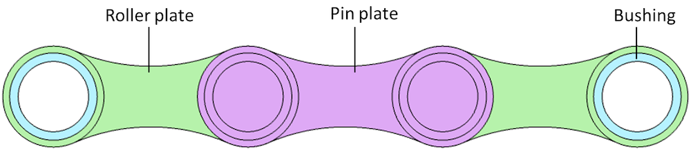
Components of a roller chain unit in 2D.
For a 3D roller chain, the constituent components are 3D link plates. Here, the roller plate is made of two hollow cylinders joined by two side plates. Similarly, the pin plate is a union of two solid cylinders joined by two side plates. A chain is formed by inserting the solid pin plates into the hollow cylindrical legs of the adjacent roller plates, producing a press-fit connection. This type of connection allows for relative rotation between the links, thereby helping the transmission of motion from one part of the system to another part. Optionally, elastic bushings between the roller and pin plates can be included.
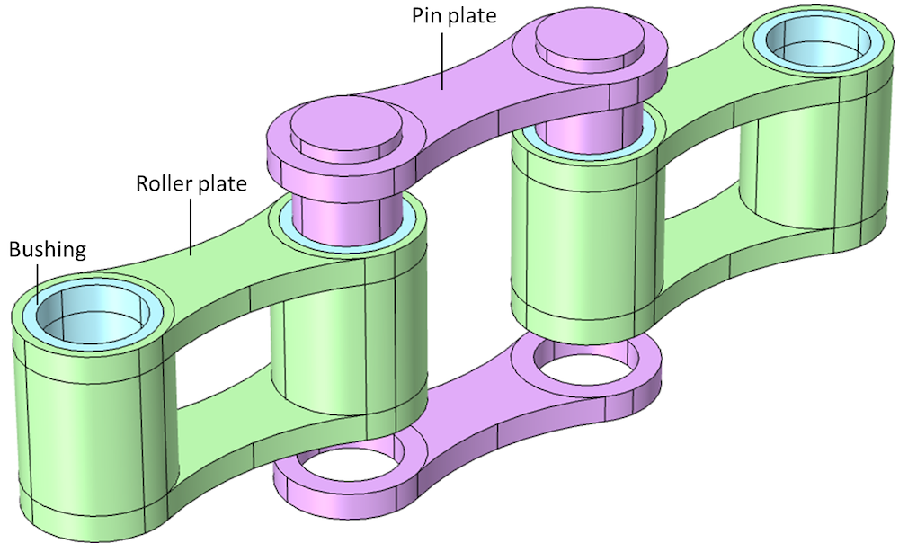
Exploded view of a roller chain unit in 3D.
Sprocket
For 2D modeling, a sprocket is a circular object with a number of teeth in which the rollers of the chain continuously engage and disengage while moving. A bore hole can optionally be created, which helps when mounting the system on external components, such as shafts. In 3D, you can also create a hub on both the top and bottom sides of the sprocket.
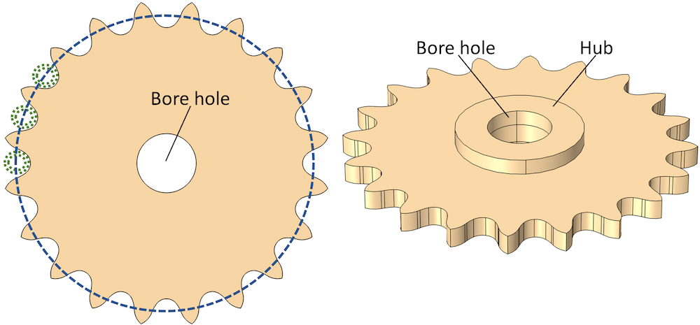
Sprocket geometry in 2D and 3D.
Roller Chain Sprocket Assembly
You don’t always need to use chain and sprocket geometry parts in combination. For some specific modeling purposes, you can even independently add either roller chain or sprocket parts to the model and combine them with other components to build some complex model geometries. On the other hand, if your interest is in simulating the dynamics of a chain drive, you don’t need to separately add and combine the chain parts; instead, there is a third built-in part of the roller chain sprocket assembly available in both 2D and 3D. As shown in the figure below, in the roller chain sprocket assembly part, the roller and sprocket geometry parts are used to create a geometry of the system with two sprockets connected by a closed loop of links.


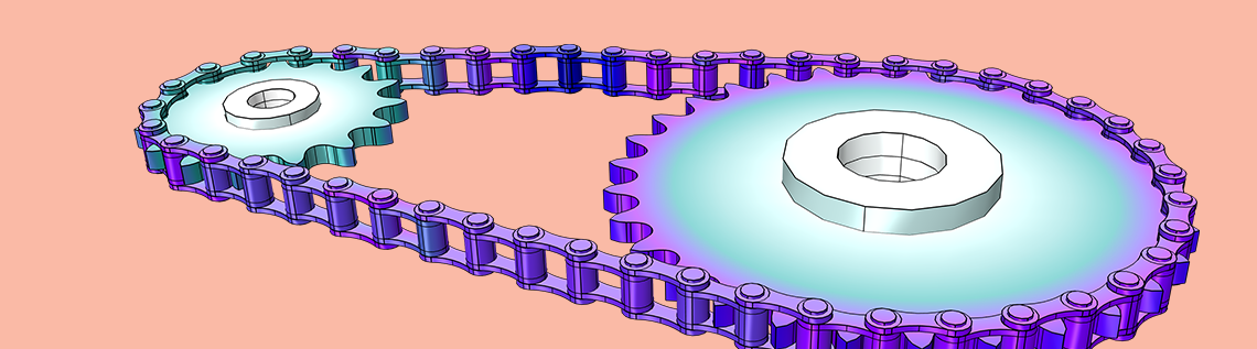
Roller chain sprocket assembly in 2D and 3D.
Adding Chain Geometry Parts from the Part Library in COMSOL Multiphysics®
The Part Library in COMSOL Multiphysics contains different geometric parts that are useful for a variety of applications, categorized under different sections. Roller chain and related geometry parts are available in the Multibody Dynamics Module section of the Part Library. To open the Part Library window, as shown in the figure below, right click the Geometry node in the model and choose Part Libraries from the Parts submenu.
To add a part to the model, click the Add to Geometry button, which adds the selected part to the model geometry as a part instance that can be used for building a parametric geometry. The Input Parameters section in the Settings window of the Part Instance shows the list of parameters used for building the geometry of the part. You can modify the default values of different parameters to build the geometry of your chain drive system. There are also options to enter the position and orientation of the part.

The Roller Chains folders in the Multibody Dynamics Module contain different geometric parts for 2D and 3D geometries. Here, the roller_chain_sprocket_assembly part in 3D is selected to add to the geometry.

A roller chain sprocket assembly added as a part instance in the geometry sequence. All of the parameters for this part are listed in the Input Parameters section.
In the following section, we look at the details of different input parameters and how they can be customized to generate different types of roller chain assemblies.
Setting Up the Geometry Parameters
Roller chains and sprockets available in the market are generally identified by a set of numbers, indicating the dimensions of different constituent components. These numbers are marked on the components or supplied along with the product. In case the information is not available, you can also measure and find out the dimensions of your chain and sprockets. Once you know the essential geometric dimensions, it is very easy to replicate them using the Part Library in COMSOL Multiphysics. Utilizing the parametric nature of the geometry parts, you can build your chain drive geometries just by entering a minimum set of parameters.
Built-in parts also provide the flexibility to incorporate certain geometric components optionally. For example, if your system does not include elements such as bushings between links, a bore hole in the sprocket, or a hub on the top and bottom sides of the sprocket, you can easily exclude them from the final geometry, just by setting the corresponding parameter to zero.
Below, we see some of the important parameters available for roller-chain-related parts and how they can be customized to build your chain drive geometries.
Roller Chain Parameters
Among all of the parameters needed for building roller chain and sprocket geometries, pitch is the most important. Pitch is the distance between the centers of two adjacent links. Many of the standards and suppliers identify roller chains using pitch dimension. The size of other chain components is mostly set as fixed ratios of the pitch. To comply with this widely accepted manufacturing practice, the input parameters of built-in parts are nondimensionalized with respect to pitch.
Some important parameters available for roller chains include:
- Pitch (p)
- Number of chain links (n)
- Sprocket width-to-pitch ratio (W)
- Roller diameter-to-pitch ratio (Dr)
- Pin diameter-to-pitch ratio (Dp)
- Minimum link plate-width-to-roller-diameter ratio (Wl)
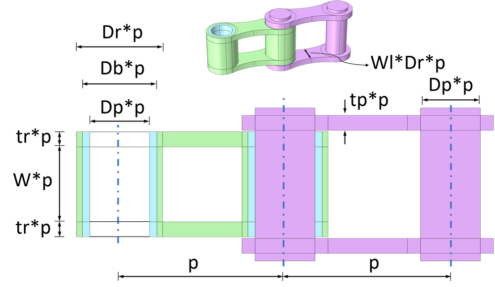
Roller chain unit with input parameters.
By tuning the above parameters, you can change the shape and size of the chain links. For example, if you want to scale the chain geometry, it can be quickly achieved by changing the pitch values. By modifying the values of corresponding link diameter parameters, it is also possible to independently change the dimensions of the roller and pin plates for the same pitch value.
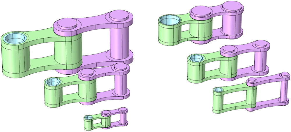
Left: Three roller chain units with different pitches and the same link diameter ratios. Right: Three roller chain units with the same pitch and varying link diameter ratios.
As you may have noticed, the shape of the side plates of some roller chains are straight, while it is curved for some other chains. By altering the minimum link plate-width-to-roller-diameter ratio parameter (Wl), both straight and curved plate geometries can be generated in COMSOL Multiphysics.
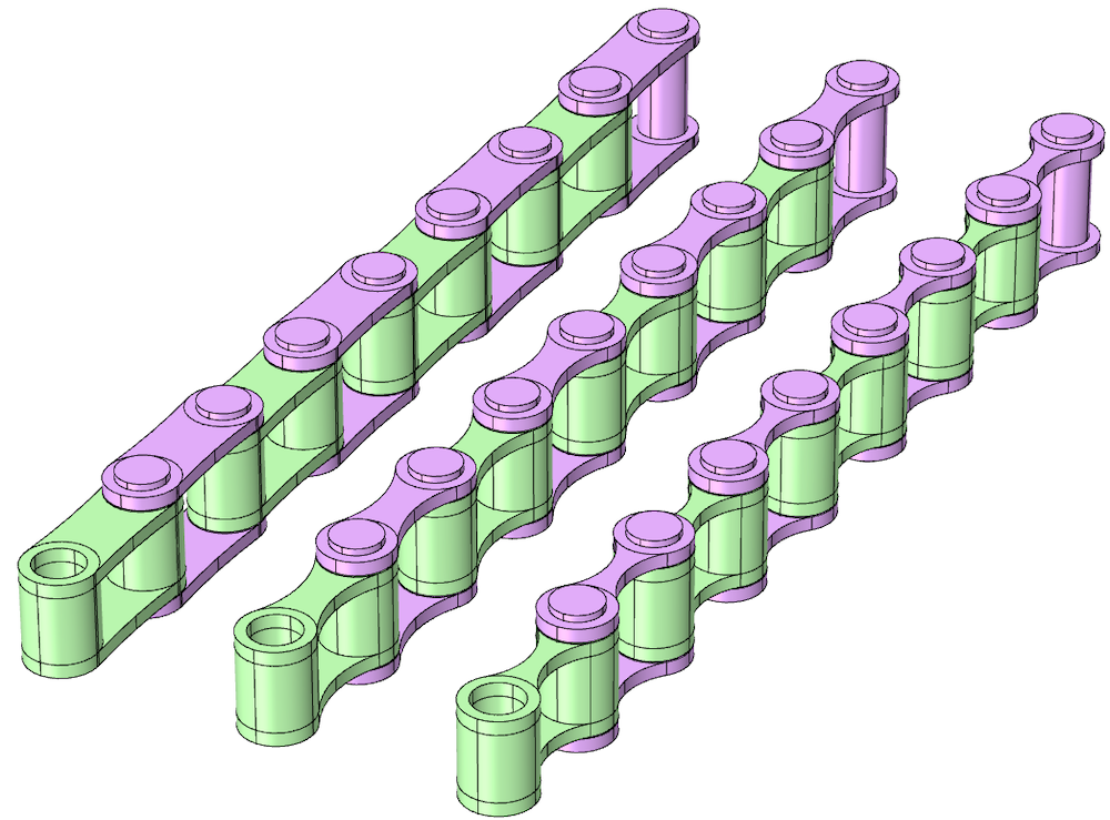
Three roller chains with different shapes of side plates. Left to right: The parameter for minimum link plate-width-to-roller-diameter ratio (Wl) is set as 0.92, 0.6, and 0.25, respectively; to build roller chains with straight or curved shapes. For all of the cases, the optional parameter Db is set to zero for no bushings between links.
Sprocket Parameters
For the chain drive to work properly, the sprockets and chain should be compatible with each other. To ensure this, the distance between centers of the adjacent teeth of a sprocket is kept the same as the pitch of the chain. Similarly, each sprocket tooth is constructed in such a way that it correctly fits the chain rollers. Also, the maximum width of the sprocket is limited to the clear distance between inner link plates. If you want, there is a parameter to incorporate some clearance between the sprocket and chain plates.
A few important parameters for sprockets include:
- Pitch (p)
- Number of teeth (N)
- Sprocket width-to-pitch ratio (Wsp)
- Roller diameter-to-pitch ratio (Dr)
- Bore-diameter-to-pitch-diameter ratio (Dbr)
- Hub diameter-to-pitch diameter ratio (Dh)
- Hub width-to-pitch ratio on upside (Whu) and downside (Whd)
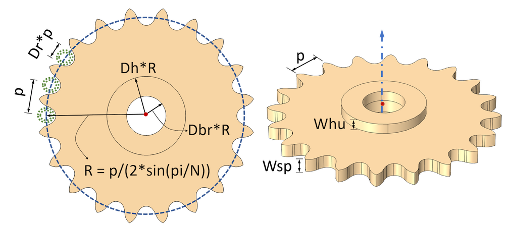
Sprocket with input parameters in 2D and 3D.
A sprocket is mainly identified by pitch and number of teeth. As shown in the figure below, you can build different shapes of sprockets by changing the combination of pitch and number of teeth.
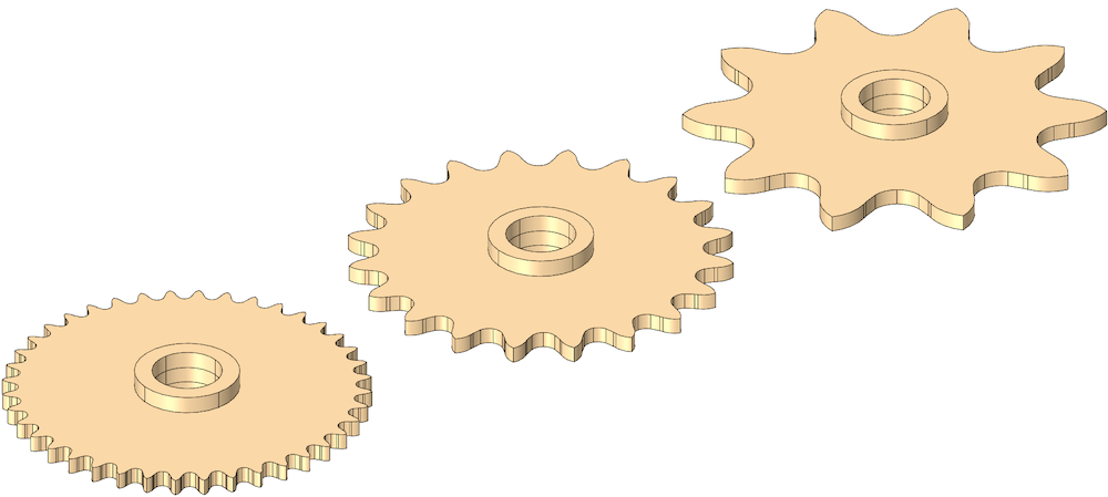
Three sprockets of the same size and different numbers of teeth.
To help mounting on shafts, the default geometry of a sprocket contains a bore hole and hub on the top and bottom sides. As shown in the figure below, you can also optionally exclude them from the geometry by setting the corresponding parameter value to zero.
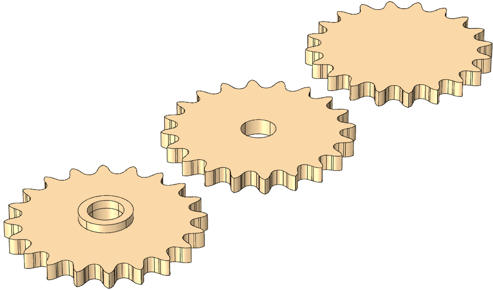
Geometry of the sprocket with different optional features. Left: Default geometry of the sprocket with a bore hole and hub; Middle: Without hub on top and bottom side; Right: Without hub and bore hole.
Roller Chain Sprocket Assembly Parameters
In addition to the aforementioned parameters required to set the individual properties of the chain and sprockets, the roller chain sprocket assembly part has a few additional parameters, mainly to control the properties of the assembly. The assembly parameters include:
- Sprocket center distance (cd)
- Number of chain links (Nc)
- Number of teeth of first sprocket (n1)
- Number of teeth of second sprocket (n2)
- First sprocket center coordinates (x0, y0, z0)
- Sprocket axis direction (esx, esy, esz)
- Sprocket clearance (clrsp)
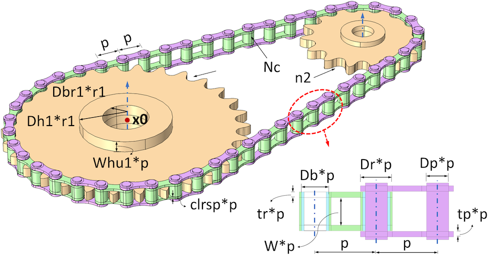
Roller chain sprocket assembly with input parameters in 3D.
Part Variants for Building Roller Chain Sprocket Assemblies
While building a chain drive, you can have different types of constraints. Imagine a case where you want to transfer the motion between two sprockets mounted on two fixed shafts. For such problems, the exact number of chain links may not be known; rather, it is calculated as the number required to cover the sprockets of a given dimension and position. In a second scenario, you want to couple two sprockets using a fixed length chain. Here, the sprocket positions are adjustable to accommodate the given chain lengths. Using different variants of roller sprocket assembly parts, you can quickly build geometry models for both cases in the COMSOL® software.
The two part variants available for roller chain sprocket assembly parts are:
- Specify sprocket center distance
- Specify number of chain links
While adding a roller sprocket assembly part to your model geometry, a window to select the part variant will appear. Depending upon your inputs, you can choose one of them and add it to the geometry.
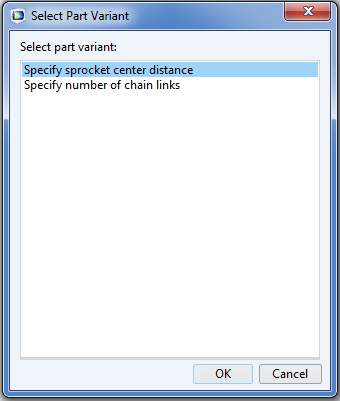
Two part variants for the roller chain sprocket assembly part.
All other input parameters except one are the same for both variants. If you use the Specify sprocket center distance variant, you need to input the Sprocket center distance (cd) parameter. Based on this, COMSOL Multiphysics builds the geometry by calculating the minimum even number of links required to wrap the two sprockets placed at a given distance. Instead, Number of chain links (Nc) is the input required for the Specify number of chain links part variant. COMSOL Multiphysics adjusts the position of the second sprocket, such that the given number of links perfectly wraps around the two sprockets.
Note that in both cases, the computation of the sprocket center distance and the number of chain links are based on nonlinear equations. Hence, there is a chance that the links may not tightly wrap around the sprockets. If you want to make minor adjustments to the center distance between the sprockets, set the center distance correction parameter (ccorr) to one and tune the value of the center distance correction factor (cdelta) accordingly.
Selections Provided by Chain Parts
We have seen how to create the geometry of various chain drive components from built-in parts. As mentioned earlier, these parametric geometry models are used to set up the physics framework required to analyze the chain drive system. To facilitate this, a set of selections are added in all of the roller-chain-related parts. Using these selections, you can easily assign different materials to different components, set up various boundary conditions, and modify the physics setup or postprocessing steps.
When you add a geometry part to the model’s geometry, all of the available selections are listed under the corresponding sections, such as Object Selections, Domain Selections, or Boundary Selections in the Settings window of the Part Instance. In roller chain sprocket parts, different object selections and domain selections are defined for roller plates, pin plates, and sprocket objects. Similarly, different boundary selections for roller plates, pin plates, and sprockets are also defined. Various predefined selections available in the roller chain sprocket assembly part are shown in the figure below. (In the second part of this blog series, you will see in detail how these predefined selections play a critical role in setting up the chain drive system).
To add any of the predefined selections to the model, use the check boxes under Keep or Physics. By selecting the check boxes under Keep, you can keep the corresponding selections in the component’s geometry. To make a selection available while defining materials and assigning physics, select the check boxes under Physics. Select the Keep noncontributing selections check box to disable the Keep column and keep all selections that do not contribute to a cumulative selection.

Different domain selections and boundary selections defined in the roller chain sprocket part. A domain selection, namely Links, composed of all chain links, is highlighted.
Checking for Building Realistic Geometries
As mentioned above, several parameters are used to build the chain and sprocket geometry parts. While entering these parameters, you need to be careful to choose sensible values within an allowable range. (For example, the values of pitch, width, or link diameters cannot be a negative number.) If not chosen properly, certain combinations of input parameters may result in unrealistic or invalid geometries. To avoid this issue, a set of Parameter Check nodes are added in each of the parts, which checks if the entered input parameters and their combinations are acceptable for a valid geometry. The geometry building happens only if all of the parameter checks are passed; otherwise, an appropriate error message with the information on how to correct the parameters is displayed.
A common check added in all parts is for positive values of essential geometry parameters. A few additional important checks for different parts are as follows:
- Roller Chain
- Roller diameter must be smaller than pitch
- Pin diameter must be smaller than roller diameter
- Bushing diameter must be smaller than roller diameter and greater than pin diameter
- Sprocket
- Number of teeth must be a positive integer
- Bore diameter must be smaller than root diameter
- Roller Chain Sprocket Assembly
- Sprocket center distance must be greater than sum of sprocket radii
- Number of teeth of first sprocket must be greater than or equal to second sprocket
If you encounter any of the above error messages, try modifying a few parameters accordingly and rebuild the geometry.
In the next blog post in our Chain Drive Modeling series, we’ll show you how to set up a chain drive using the Multibody Dynamics Module. Stay tuned!
Next Steps
Browse these additional resources:
- Learn about building model geometries using the geometry parts in COMSOL Multiphysics: Using Geometry Parts and Part Libraries in COMSOL Multiphysics®
- Read this blog series on gear modeling
- Explore the updated features and functionality in the Multibody Dynamics Module as of COMSOL Multiphysics version 5.5 via the Release Highlights
Editor’s note: We have published the follow-up post in this blog series. Read it here: “How to Model a Chain Drive in COMSOL Multiphysics®”.

Comments (0)