

This is Part 3 of a blog series on how to handle selections and entity numbers when using LiveLink™ for MATLAB® and the COMSOL® Application Programming Interface (API). In this section, I’ll discuss how the internal handling of selections and entity numbers in COMSOL Multiphysics® simulation software is performed and how you can utilize these methods when setting up your own models.
Automatic Handling of Selections in a Model
When you make a change to a model, including changes to the geometry, COMSOL Multiphysics keeps track of most settings you have applied to the model and their associated selections. If you have a boundary condition applied to a set of boundaries, then the model remembers these settings — and even updates the entity numbers of the boundaries when they change due to changes to the geometry.
Of course, there are cases when settings can’t be kept. For instance, if you delete all boundaries that a certain boundary condition applies to, then the boundary condition will have an empty selection. Thus, it will not contribute to the model unless you manually add new boundaries to its selection.
In Part 2 of this blog series, we showed you a method of using coordinate-based selections using functionality in LiveLink™ for MATLAB® to obtain entity numbers for setting up models. This is very easy to work with on the command line, but when working with selections in COMSOL Multiphysics, it is much easier to add selections via the user interface (UI) and then apply the physics settings to these selections rather than to the geometric entities. This way, you are leveraging the internal framework that keeps track of geometric entities and you do not need to use entity numbers when setting up a model.
There are two ways to add a selection to a model. The first method is to select the Create Selections check box that is available for every geometric operation.
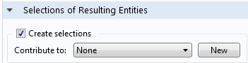
This way, you can easily create selections that contain the output entities of the operation. Selections will be created for domain, boundaries, edges, and points. The name of the selections will consist of the tag of the geometry and object plus “_dom”, “_bnd”, “_edg”, and “_pnt”. For instance, for a rectangle with the tag r2 the tag of the boundary selection becomes geom1_r2_bnd.
The second method of adding selections to a model is to create named selections in the model tree. These can be added as nodes in the Definitions branch of the model tree, as well as in the geometry sequence itself. It doesn’t matter very much where you add named selections, but selections in the geometry sequence can not only be used for physics or mesh settings but also as input to downstream geometry operations. By choosing descriptive names, you can obtain a good overview of the geometry sequence itself.
Using COMSOL Multiphysics Selections to Track Changes to the Geometry
Let’s take a look at a named selection in the geometry sequence. Navigate to the Geometry 1 node in the model tree and right-click, then click on “Selections”. Upon doing so, you’ll see a list of different selection types:
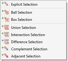
The Box Selection corresponds to the command mphselectbox, but since this selection is more tightly connected to the COMSOL Multiphysics geometry, it has more options. You can choose to include the entity either if anything is inside the Box or if something is inside it. You can also group by continuous tangent, which allows you to select adjacent faces or edges that have continuous tangent (by some tolerance). I will not use these advanced features in this example.
For the example model of the heat sink, I will add two selections: one selection for the hot part of the heat sink and another selection for the cold side. In comparison, I made three calls to mphselectbox in Part 2 of the blog series. In order to get the hot selection, I simply select the check box for Create Selections for the rectangle that defines the first component. Since this rectangle is used in an Array operation, the selection is automatically extended to cover all parts of the array. For the cold side, a Box Selection is added to the end of the geometry sequence to include the upper part of the heat sink. Now, even if I add more fins — more rectangles — to the heat sink, the box selection will automatically include them, since it is the last node in the geometry sequence.
")
Box Selection configured to output the boundaries that fall within the specified limits, in this case the cold side of the heat sink.
After having set up the selections, the boundary conditions in the model have to be configured so they utilize the selections. From now on, the geometry can be updated without having to worry about the selections or the entity numbers that COMSOL Multiphysics uses internally. Now the model can be saved and used both from within the COMSOL Multiphysics® UI and from the MATLAB® software. Setting up the selections can, of course, also be carried out using the COMSOL API. To see how this is done, you can simply save the model as a model file for MATLAB® software, as described in Part 1 of the Working with M-Files series.
When you load a model that contains selections using LiveLink™ for MATLAB®, you can view the selections using the wrapper function mphviewselection. To see the selection for the cold side, you can execute mphviewselection(model,'geom1_boxsel1').
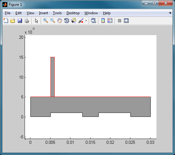
Boundaries (in red) output by the box selection for the cold side of the heat sink when viewed using the command mphviewselection.
Simulation
In the example in Part 2, I modified the geometry by adding more fins to the heat sink. Instead of using mphselectbox multiple times for each version of the geometry as I did there, here I add the selections to the model just once and leave the hard work of updating geometry and selections to the software.
First, you load the model into MATLAB® software using the mphload command:
![]()
It is very simple to write the code for changing the geometry and solving the model. By using the built-in COMSOL Multiphysics® software selections, there is no need to adjust anything when using MATLAB® software for updating the model. Thus, the loop becomes shorter than before:
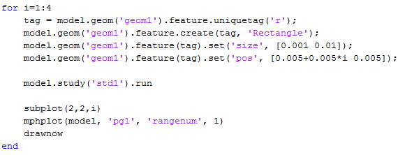
Running this script produces the results plot shown below.
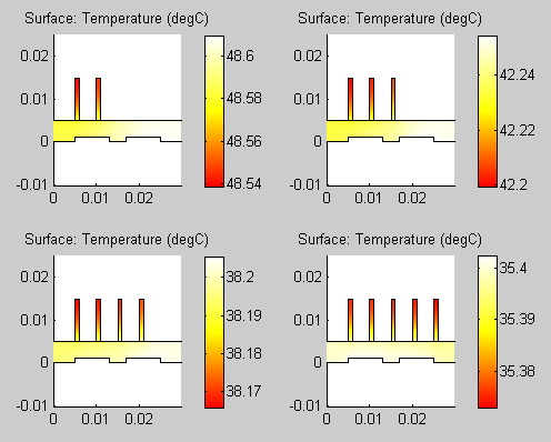
Temperature distribution in the heat sink for different fin configurations.
Verifying Selections
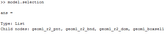
You can verify the settings that are included in a model by writing “model.selections”. MATLAB® software will write the names (tags) of the selections in the model:
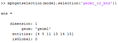
You can find out what a selection contains by using the “mphgetselection” function, which for the geom1_r2_bnd selection gives this result:
What We Have Learned About Working with M-Files
There are several ways of making sure that selections for model settings are preserved when you introduce large changes to a model geometry. Using commands that come with LiveLink™ for MATLAB®, you can keeping track of the entity numbers within specified coordinates. The downside of this approach is that you then have to continue using these commands for updating the geometry. The method will break down if you load the model into the COMSOL Desktop® environment. If you instead rely on named selections in the model tree, you can obtain the same result and also have the ability to work with the model both at the MATLAB® software command prompt and in the COMSOL Desktop®.
If you’ve been wondering whether or not we can do without entity numbers in selections, the answer is “Yes.” As you saw here, we can indeed do without manually fiddling with entity numbers in selections. It takes a little work to include named selections in the model, but they offer better usability and robustness.
Other Posts in This Series
MATLAB is a registered trademark of The MathWorks, Inc. All other trademarks are the property of their respective owners. For a list of such trademark owners, see http://www.comsol.com/tm. COMSOL AB and its subsidiaries and products are not affiliated with, endorsed by, sponsored by, or supported by these trademark owners.

Comments (2)
Oscar Diaz
November 3, 2015hej Lars,
My models are generated in a Matlab code that runs cyclically, updating geometries and BD conditions (voltages) for a 3D electrostatic simulation. I have noticed that given the complexity of my geometry, some times some selections end up empty after a geometric boolean operation. I have not been able to find what is causing the problem or if is there any other way I can define my geometry so all elements/selections are the way I want in the final domain for the case solution.
why does it happen? Am I doing something wrong with the boolean operations so some of my selections are empty and then I cannot assign them any BD props?
Thanks
Lars Gregersen
November 4, 2015 COMSOL EmployeeHi Oscar
It is hard to tell what goes wrong without having seen your model and Matlab code. You can send your model to support and we will have a look at it.
Selections often do unexpected things if you somehow make too large changes to your geometry such that e.g. unions or intersections become unexpectedly empty.
The easiest way to verify that your model is correctly set up for a certain set of dimensions is to save the model (once you have constructed it using your Matlab code) as an MPH-file and open the model in Comsol.