When stresses in a structure exceed acceptable limits, the first thing that comes to mind is to add more material to increase the load-carrying capacity. While this is often a good choice, there are also a number of cases when you should follow the opposite path: improve the structure by removing material. In this blog post, we investigate some such examples.
The Mystery of the Added Holes
About 30 years ago, I analyzed the stresses in a type of centrifuge. The problem was that the stresses around some holes (through which one of the substances being separated was to be ejected) were too high. When I suggested to the customer that they could solve the problem simply by adding even more holes (which would actually also improve the throughput), they did not look fully convinced. However, some more FE analyses proved the point. In principle, the structure looked like this:
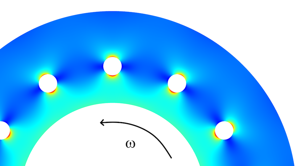
Conceptual view of part of the centrifuge, together with the von Mises stress distribution. The loading is caused by centrifugal forces.
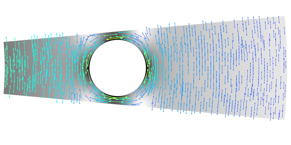
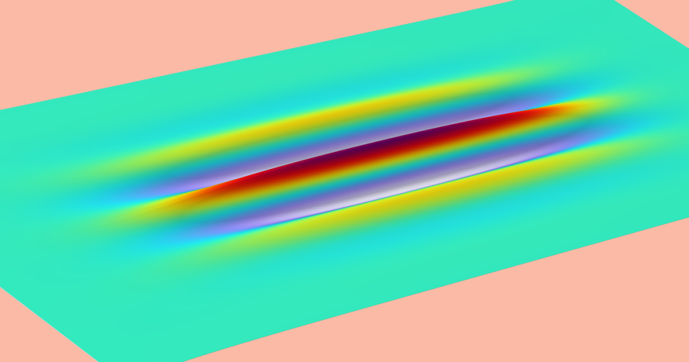
By adding principal stress arrows to the plot, it is possible to get a better understanding of what is really going on:
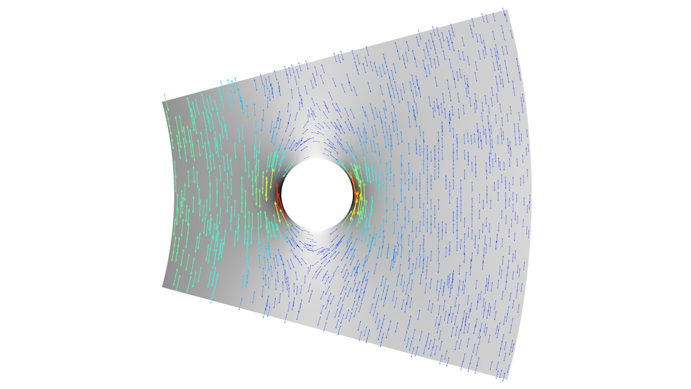
Plot of the largest principal stress in the original geometry, having 12 holes around the circumference.
The main stress component is acting in the circumferential direction, and stress concentrations are caused by redirection of the stress flow. Actually, if we could replace the holes with a circumferential slit, there would be no stress concentration at all. However, that is not possible, since the inner and outer parts of the ring must be connected. If we move the holes closer to each other, there will be less redirection of the stress flux. The best distribution of the holes can be found using an optimization procedure, but in this case, it is easy to just change a parameter manually. It turns out that 34 holes is a good number.
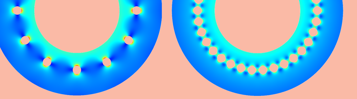
With 34 holes, the von Mises equivalent stress is reduced by 33%. At the same time, we get a lighter structure with a better throughput.
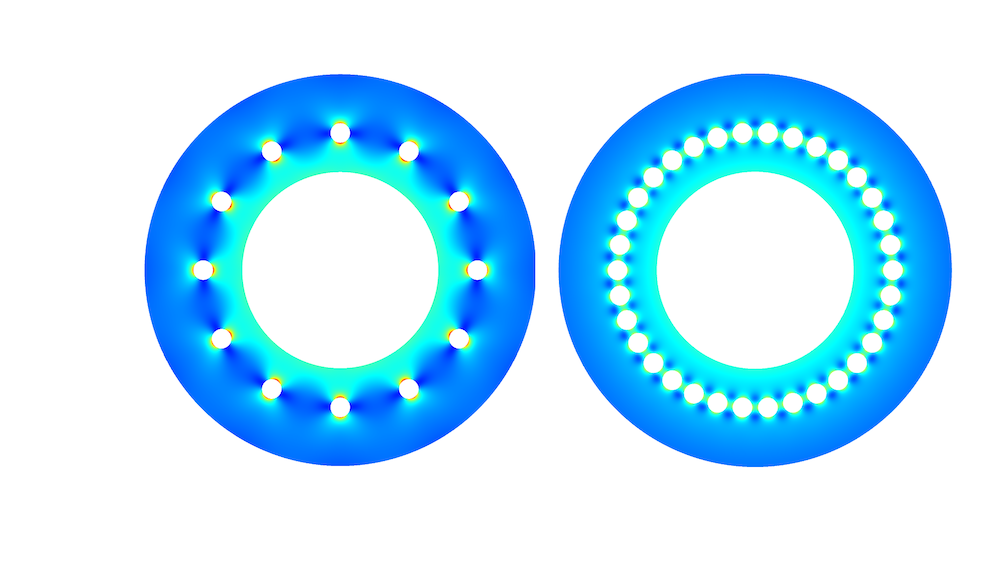
Comparison of the von Mises stress in a centrifuge with 12 holes and 34 holes.
Looking at a closeup of the principal stresses reveals why we cannot put the holes even closer: The ligament between them gets subjected to radial stresses caused by the centrifugal forces, so it cannot be made thinner.
The largest principal stress when 34 holes are used.
Fillets
Stress concentrations occur where there are abrupt changes in a geometry. An experienced designer will try to make the transitions as smooth as possible and use large fillet radii. Increasing a fillet radius, however, may not be feasible, since the added material can interfere with other parts.
If this is the case, you can use a design called an undercut or relief groove. In this case, you increase the radius by removing material. (Note that in the context of welding, “undercut” usually means a certain type of weld defect.)
In the example below, you can see three different designs. In the original design (top), the stress concentration factor is 1.91. By increasing the fillet radius by 50%, the stress concentration factor can be reduced by 13% to 1.67. The red dashed lines show from where the thickness of the thin part is constant, so by increasing the fillet radius, some space is lost.
In the third case, an undercut with a larger radius has been used instead. This gives the same reduction in stress concentration, but without the drawback of extending the thickened region. The downside of using undercuts is that the manufacturing of the part can be more complicated and thus expensive.
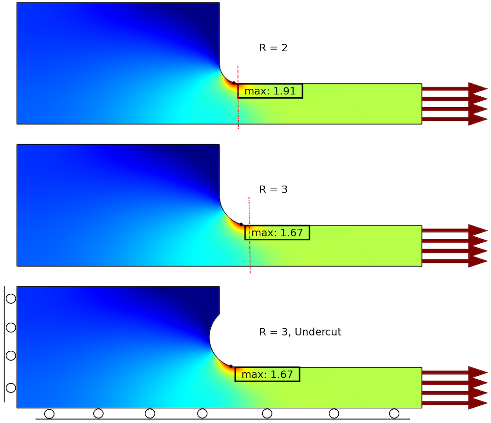
Reduction of stress concentration using two different geometrical changes.
A special case where a relief groove can be very efficient is in welds. Since the weld itself is usually very sensitive to fatigue, it may be possible to shield it by adding a groove in front of it. Actually, due to the difference in fatigue strength, it may be possible to allow a significantly higher stress at the groove than what would have been the case at the weld toe.
Displacement Control
When the loading on a structure consists of a controlled displacement, rather than a prescribed force, adding more material will generally just increase the forces. The stresses will be constant, or even increase. There are many situations in which it may not seem like the displacement is controlled at a first glance, but it still is. Thermal deformation can often be considered a type of prescribed displacement.
Consider the following 2D example:
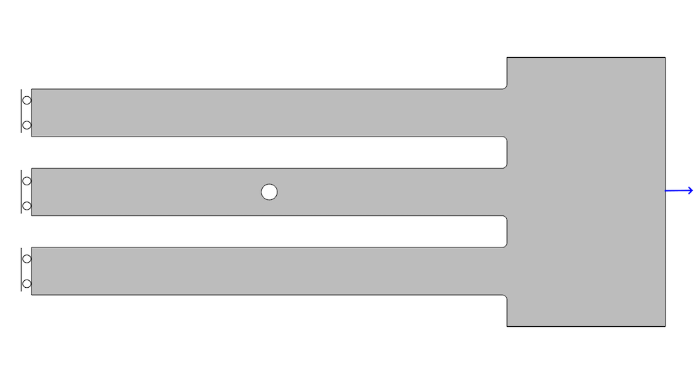
Geometry and boundary conditions.
The three bars are stretched by a prescribed displacement of 0.1 mm at the right-hand side. On the left hand side of the model, a symmetry plane is assumed. The resulting stress distribution is shown below.
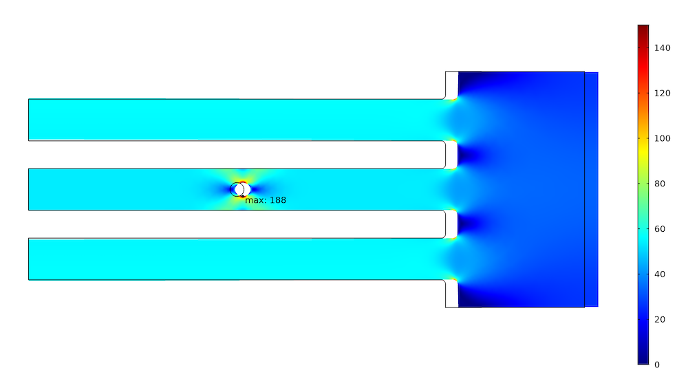
Stress distribution under prescribed displacement (deformation is magnified by a factor of 100).
The maximum stress at the hole is 188 MPa. The force in the two outer bars is 3.36 kN, while the force in the central bar is 3.22 kN. We can now try to lower the force and thus the stress in the critical central bar by reducing its stiffness. This can, of course, be achieved through a multitude of different geometrical changes. In reality, the options are usually limited by the function of the structure. Here, we make a notch with a large radius at the symmetry plane.
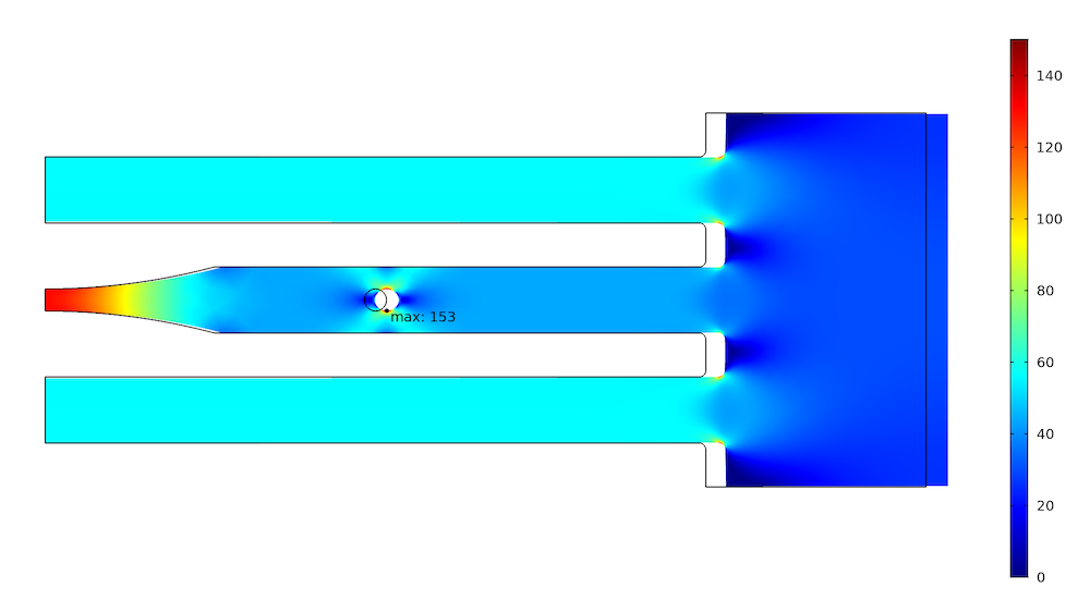
The effect of the change is a reduction of the maximum stress by 19% to 153 MPa. It is clear that it would be easy to achieve an even larger reduction by removing more material.
What happened in the other two bars? Due to the prescribed displacement, they should not be stretched more than before. Investigating the force shows that it actually increased to 3.36 kN; that is, by less than 1%. The reason for the slight increase is that the prescribed displacement is not applied directly to the bars, but through an elastic but rather stiff structure. This is usually the case in real-world structures.
Changing the Load Path
Let’s consider the same geometry as in the previous example. Instead of a prescribed displacement, a force is used as the load. The value is selected to exactly match the reaction force that was caused by the prescribed displacement; that is, 9.94 kN. Obviously, in the original geometry, the results will remain the same.
In this case, however, when we reduce the stiffness of the middle bar, more load must be carried by the two outer bars. Also, since the total stiffness of the structure is reduced, the displacement at the loaded boundary must increase somewhat.
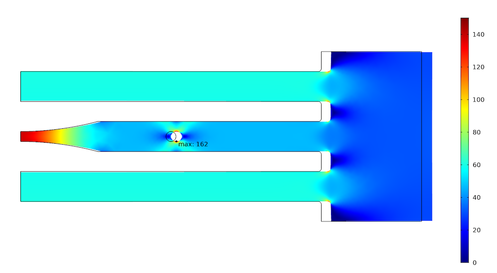
Stress distribution in the softer structure when a force is prescribed.
As can be seen, the reduction in peak stress is now smaller. The force in the outer bars has increased to 3.58 kN, while the force in the central bar is 2.77 kN.
This is an example of a completely different mechanism: a change in the load path. It is possible to reduce the force in the critical member by transferring force to the other members. An easier way to achieve this would be to thicken the two outer bars, but that is outside the scope of this blog post, since it means adding rather than removing material.
Final Thoughts on Making Structures Stronger
Removing material can be beneficial for reducing local stress levels in several situations. As can be seen in the examples above, it does, however, often come with an increased manufacturing complexity.
In the examples above, the changes were made using engineering intuition. By using methods like parameter, shape, or topology optimization, even better results can be obtained. Additive manufacturing methods can then make the production of complex geometries feasible.
Learn more about the functionality available for performing mechanical analysis in the COMSOL® software.


Comments (5)
Temesgen Kindo
February 19, 2020Henrik, this is beautiful! Thanks for sharing.
Matthias Frische
February 24, 2020Very nice !! Thank you !!
When I was young I worked for a Porsche racing team we had a similar problem with stub axles that broke off…
it was fixed by removing material… at that time that was counterintuitive for me 🙂 http://www.jpf.de/jpf/joest/page_01.htm
Marketing Speculum plast
February 27, 2020The given information is very useful and precise.thank you for this wonderful information. eagerly waiting for a new post so that we get more information on the relevant topic.
Qian Zhang
May 3, 2020Excellent demonstration. Could you share this demonstration as an example for users to learn? Thanks.
Henrik Sönnerlind
May 6, 2020 COMSOL EmployeeThe example models are currently not available, but I can upload them to the Application Gallery within a few days.
Henrik