
Thermoelectric coolers come in various types and sizes, including single-stage and multistage devices. Their application area is large, as they are used in both consumer products like cooling boxes and as temperature controllers in satellites. If you are looking to analyze the design of a thermoelectric cooler and optimize it for a specific application area, a simulation app is an efficient way to accomplish your goals. We discuss how to use the Thermoelectric Cooler demo app in this blog post.
What Is the Thermoelectric Effect?
The thermoelectric effect is the conversion of a temperature gradient into an electric voltage and vice versa. The ratio of how an applied temperature difference results in an induced voltage is described by the Seebeck coefficient S(V/K). In principle, all materials have a Seebeck coefficient S \neq 0, but a few of them have coefficients significant enough to be useful. If a material is suitable for thermoelectric applications, it is not determined by the Seebeck coefficient alone. A high thermal conductivity \kappa works against the thermoelectric effect and a high electrical conductivity \sigma amplifies it. The figure of merit, Z, determines the efficiency of a material:
Seebeck discovered in 1821 that temperature differences lead to electricity. In 1834, Peltier discovered that heating or cooling occurs when an electric current is present. Finally, Thomson determined that the Seebeck coefficient is temperature dependent and the heat produced is the product of current density and temperature gradient. These effects, known together as the Seebeck, Peltier, and Thomson effects, form the general formulation of the thermoelectric effect that is used in the COMSOL Multiphysics® software. Modeling the thermoelectric effect also means that Joule heating must be considered (this is done in COMSOL Multiphysics by default).
Designing Thermoelectric Coolers
Thermoelectric coolers, also known as Peltier coolers or TECs, are mainly used for cooling purposes, but can also be used for heating or as temperature controllers. The main advantage of a TEC is that it is almost maintenance free because there are no moving parts or liquids. They are also useful to cool devices where other methods of cooling, such as air or coolant flow, are impossible to apply. On the other hand, they are made from relatively expensive materials and do not provide efficient cooling effects in relation to their manufacturing costs. Therefore, optimizing the performance of thermoelectric coolers is an important design task.


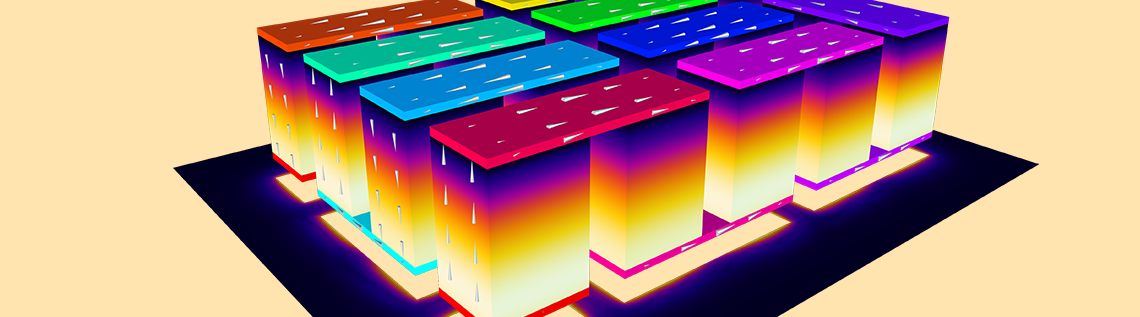
The geometry (left) and temperature profile (right) of a thermoelectric cooler.
The basic design and operating principle of a thermoelectric cooler is depicted in the figures above. The device is made up of an alternating array of p-type and n-type semiconductors (thermoelectric legs) that are electrically connected and sandwiched between thermally conductive plates.
Building an App to Analyze Thermoelectric Cooler Designs
Thermoelectric coolers are often used in products when there is limited space for cooling devices. When designing the app, we should keep in mind that the app user needs to be able to change the size of the thermoelectric cooler geometry. Just as the overall size is variable, the size of the legs and the thickness of ceramics and conductors should be variable too. Different thermoelectric materials exist and the app user should be able to select between different options to accurately represent the design. Depending on the application, the temperature of the hot side differs, which influences the material properties and hence the thermoelectric behavior. The app should also have inputs for these different variables.
Considering TEC Design Parameters
There are common parameters that characterize the efficiency of a thermoelectric cooler, including:
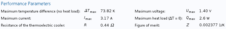
- The figure of merit, Z (mentioned above)
- Maximum temperature difference between the hot and cold sides, \Delta T_{\textrm{max}}
- Electric current required to achieve the maximum temperature difference, I_{\textrm{max}}
- Corresponding voltage, U_\textrm{max}
- Overall resistance, R
- Maximum heat load, Q_\textrm{max}
Besides these values, several performance charts are of interest when analyzing a thermoelectric cooler’s performance. For instance, \Delta T depends on the heat load Q and the applied current I. The coefficient of performance (COP), defined as
gives the most efficient TEC performance when the heat that is absorbed divided by input power is at its maximum. Curves describing how COP depends on I help us choose thermoelectric cooler parameters that are suitable for a certain application.
After running the app, the computed results are displayed in the Graphics section of the user interface (UI). The app automatically shows the temperature plot together with the performance parameters.
Here is a screenshot of the app UI showing the performance parameters for the default thermoelectric cooler design:
Three separate tabs display the performance charts for the temperature difference depending on the heat source (\Delta T(Q)), the temperature difference depending on the applied current \Delta T(I), and the coefficient of performance.


Performance charts for the thermoelectric cooler design with default inputs. Left: Dependence of the temperature on the applied current. Right: The coefficient of performance for three different temperature differences.
The Thermoelectric Cooler app, built using the Application Builder in COMSOL Multiphysics, combines all of these inputs and outputs into a user-friendly interface.
Video (without sound) demonstrating the Thermoelectric Cooler app in use.
Behind the app, there is an underlying fully parameterized COMSOL Multiphysics model. When changing the geometry in the app, the mesh, physics, and results adapt automatically. When you press the Compute button, it starts four studies that find the performance parameters and results that are of interest. In addition, the app provides information about the computational time. We can also create reports and generate PDF documentation directly from the app.
Optimize Your Own Designs with Apps
The Thermoelectric Cooler app serves as a starting point and inspiration for your own app-building process. Although this app is limited to a single-stage thermoelectric cooler within a certain size range, you can modify and reuse the existing geometry sequence for a second- or third-stage cooler. This way, it takes little effort to extend the app to a multistage thermoelectric cooler.
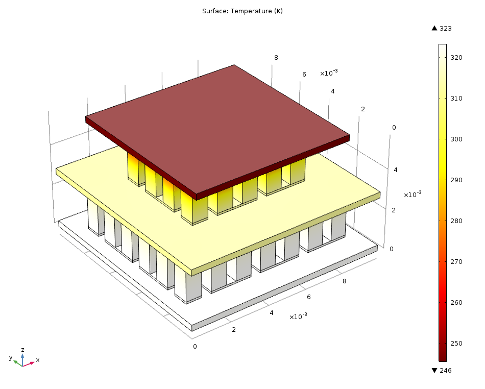
The temperature distribution in a two-stage thermoelectric cooler.
With just a few steps, you can also enable users to input user-defined material data or provide additional predefined materials. For more extensive analyses, you can set intervals in the app so that users can perform multiple parametric analyses at once. There are almost endless possibilities for extending the capabilities of this app and all of the apps you can access in the Application Library.
Try it yourself and let us know what you come up with!
Further Reading
- Find more app inspiration by browsing the Applications category of the COMSOL Blog
- These previous posts are especially helpful for app design:
- Watch our introductory video series on the Application Builder


Comments (0)