
Whenever you are modeling the geometry that you will use for your COMSOL Multiphysics analysis, either with the native CAD creations tools in the COMSOL software or using another CAD system, you may end up with a geometry that has more features than you really need. Here, we will look at a set of features called Virtual Operations that will let you quickly and easily simplify any CAD data in preparation for modeling and meshing.
What Is CAD Geometry and How Is It Used?
When we use the term CAD geometry, we are referring to a set of data structures that provide a very precise method for describing the shapes of parts. This method is called boundary representation, or B-rep. A B-rep model for solids consists of topological entities (faces, edges, and vertices) and their geometrical representation (surfaces, curves, and points). A face is a bounded portion of a surface, an edge is a bounded segment of a curve, and a vertex lies at a point.
In the B-rep data structures, surfaces are often represented by Non-Uniform Rational B-Splines, or NURBS. The B-rep model of a part is used as the basis for other operations, such as generating tooling paths in Computer Aided Manufacturing software, creating Rapid Prototyping files, and — most importantly — for your COMSOL Multiphysics modeling, generating the finite element mesh.
Your first choice in terms of element type will usually be the tetrahedral mesh for 3D models or a triangular mesh in 2D models. Any 3D geometry can be meshed with tetrahedral (“tet”) elements and any 2D geometry can be meshed with triangles. Additionally, these are the only elements that support Adaptive Mesh Refinement.
For the rest of this blog post, we will focus on the 3D case, since it is the most computationally challenging. At a very conceptual level, the COMSOL tetrahedral meshing algorithm first applies a mesh on all of the surfaces of an object. This mesh is then used to “seed” the volume mesh from which tetrahedral elements “grow” elements inwards. As these tetrahedral elements intersect, their sizes are adjusted with the objective of keeping the elements as isotropic (similar edge lengths and included angles) as possible and to have reasonably gradual transitions between smaller and larger elements.
An issue that you can run into with this algorithm is that the meshing is done based upon the underlying topological entities. There is no way for the meshing algorithm to insert larger elements if the underlying entities are small. As we saw in the previous blog post “Working with Imported CAD Designs,” we can use the CAD repair and defeaturing tools to simplify the geometry.
However, when these algorithms attempt to remove topological entities, they often need to modify the underlying NURBS surfaces and are therefore somewhat limited. An alternative in COMSOL Multiphysics software is to use Virtual Operations, which can keep the existing geometrical representations as a basis for constructing a new alternative topological structure purely for the purposes of meshing and defining the physics.
What Can You Do with Virtual Operations?
Let us take a look at the virtual operations and see what you can do with them through a series of examples. The first ten options in the Virtual Operations menu actually only represent five unique capabilities, but they can be used in different ways.

The Virtual Operations menu.
Let’s look at a quick example for each of these five.
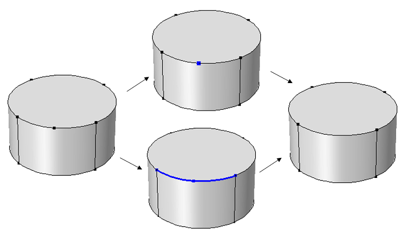
Ignore Vertices and Form Composite Edges
The below image demonstrates the Ignore Vertices feature (top) and the Form Composite Edges feature (bottom), which result in the same geometry.
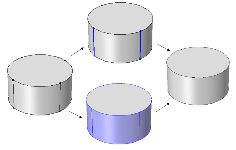
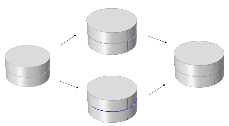
Ignore Edges and Form Composite Faces
Below is a demonstration of the Ignore Edges feature (top) and the Form Composite Faces feature (bottom), which result in the same geometry.
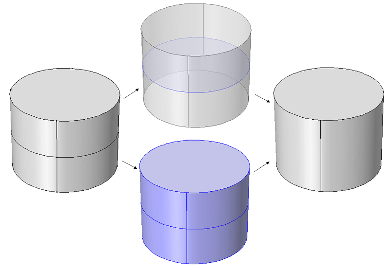
Ignore Faces and Form Composite Domains
The following image demonstrates that the Ignore Faces feature (top) can be used to ignore any faces that lie between two adjacent domains, resulting in a single domain. The Form Composite Domains feature (bottom) will also combine multiple domains into a single domain.
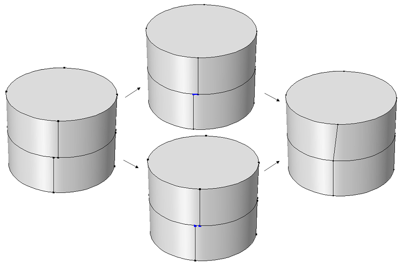
Collapse Edges and Merge Vertices
As shown next, the Collapse Edges feature (top) and the Merge Vertices feature (bottom) will result in the same geometry. The Merge Vertices feature gives the additional option of choosing which vertex to remove and which one to keep.
Collapse Faces and Merge Edges
The Collapse Faces command (top) and the Merge Edges command (bottom) stand out, since they have been designed to work even in those cases where the faces are not continuous. A useful application for these commands is to get rid of slivers resulting from the union of components that are slightly misaligned or do not fit for other reasons.
Mesh Control Operations
Lastly, the Mesh Control Points, Edges, Faces, and Domains features will hide points, edges, faces, or domains during the set-up of the physics; however, these geometric entities will still be present during the meshing step. By using these operations, you can gain greater control over the meshing process by designating geometric entities for the control of the mesh size and distribution. The physics set-up is kept simple by excluding the control entities. A typical area of application is in CFD simulations, where regions of steep gradients in a volume need a high mesh density.
A Model Example
It appears that we have a lot of options here, and you may wonder which of these features you should be using. In practice, the Form Composite Faces can usually be your first choice. Almost all of the issues that you will typically run into, with the exception of forming composite domains, can be handled with this feature.
Let’s look at a case from the COMSOL Multiphysics Model Library: the stresses and strains in a wrench. This is a structural model of a combination wrench. The provided CAD geometry has some relatively complex sculpted surfaces and fillets and blends, which result in small faces in some parts of the model. These small faces force the tet mesher to use smaller elements, but we can see that Virtual Operations can be utilized to avoid this.
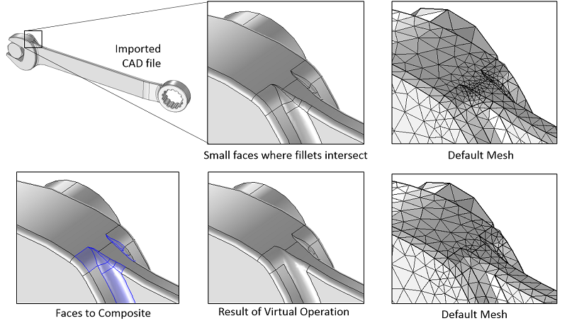
A detailed view of a CAD file shows that small faces result in a fine mesh. Using the Virtual Operations allows larger elements in these regions.
We can use the Form Composite Faces feature to abstract whole sets of faces. You can simply select all of the faces and then deselect those faces that you do not want to abstract. This is acceptable and recommended if you know you do not need high fidelity of the mesh in certain regions where there are many small faces.
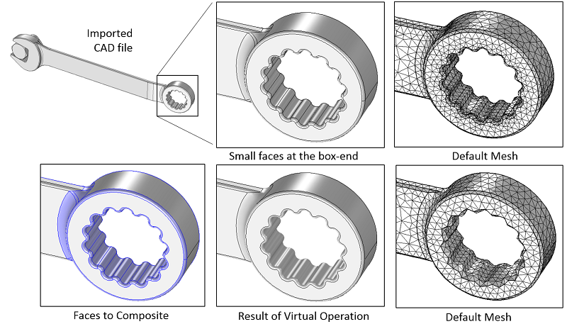
Virtual Operations can be used to combine sets of surfaces and significantly simplify some parts of the geometry.
Summary and Next Steps
We have now seen why you would want to use these Virtual Operations and the many ways in which they can be used. If you want to see a step-by-step guide for using these features to simplify your geometry, please see the Model Library example on using Virtual Operations on a Wheel Rim Geometry.


Comments (4)
David Cortes
December 3, 2018Excellent
Youssef Aider
May 13, 2019thanks but i have a question. if i add a mesh control domain, and there are shared boundaries between my virtual and real domain, the boundaries just goes with the virtual mesh domain. and there is no way to redo the boundaries, the virtual mesh domain will always remove any boundary and domain done there.
Zheng Huang
December 8, 2020Any further introduction/tutorial about the mesh control entities?
Jose Martin
January 26, 2022Computer-Aided Design or CAD is the most common tool used in 2D and 3D design. The article successfully articulates the importance of a new set of virtual operations features that simplify CAD data preparation for modelling and meshing. CAD geometry refers to a group of data structures used to model shapes of parts, describing them with precision. Setting up precise data structure is also known as boundary representation or B-rep. A face is a bounded portion of a surface, an edge is a fixed segment of a curve, and a vertex lies at a point. Virtual Operations can help you ignore vertices and form composite edges, ignore edges and form composite faces, ignore faces and form composite domains, collapse boundaries and merge vertices, collapse faces and blend edges, and more.