
Today, guest blogger and Certified Consultant Giuseppe Petrone of BE CAE & Test discusses creating apps to perform thermal analyses of electronic devices.
When manufacturing electronic devices, leading companies often look to simulation in order to thermally characterize their products. At BE CAE & Test, we have found a more efficient way of answering such requests: designing apps that are tailored to our customers’ needs. Our surface-mount device app, presented here, is just one testament to what apps can achieve.
Simulation Apps: A New Frontier in Virtual Prototyping
An innovative concept came about some time ago at COMSOL. What if a standard finite element model could be turned into an intuitive simulation tool that was accessible by a broad audience? The “from model to app” idea came to fruition with the release of the Application Builder.
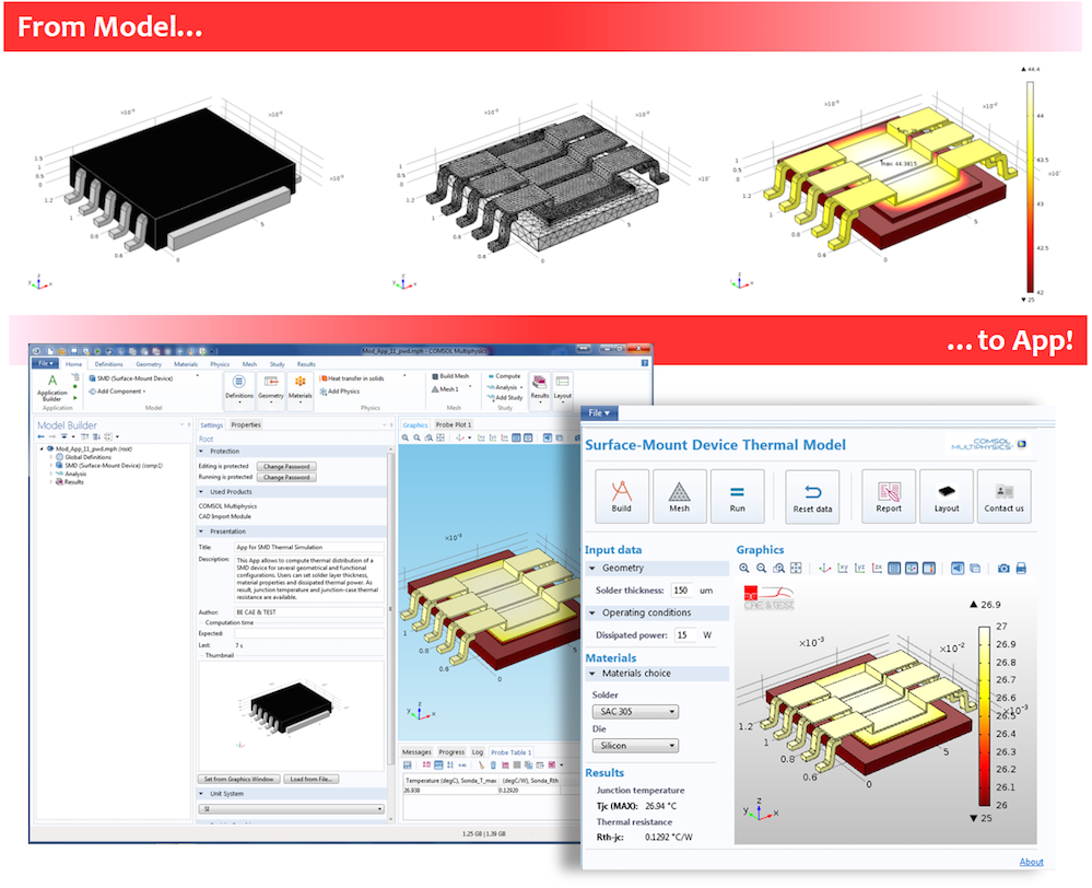
With the Application Builder, you can turn your model into an easy-to-use app.
Apps mark a revolutionary page in the history of simulation. With these flexible and user-friendly tools, people of varying levels of expertise can access, exploit, and share simulation power. As such, simulation apps can create more business opportunities with customers. Beyond simply providing them with a technical report, you are also supplying them with an interactive tool.
We at BE CAE & Test strongly believe that apps represent the natural evolution of numerical simulation applied to real-world physics. Trusting this concept, our goal has been to promote the use of apps, which has included performing demonstrations for customers.
What Is a COMSOL App?
When proposing the idea of a simulation app to customers, one of the first questions they often ask is: “What is a COMSOL app?”
In our opinion, an app can be defined as a customized user interface (UI) that allows users to carry out parametrical simulations without building models. For “parametric” analyses, you have the flexibility to select a wide variety of parameters to include in your app’s design, which app users can then easily manage and modify through the interface. Such parameters can range from geometries and materials to model assumptions and individual functional working conditions (i.e., source terms).
While apps are designed to hide the complexity of the underlying model, they still provide you with the functionality to fully exploit all of the visualization features available in COMSOL Multiphysics, making it easy to communicate results.
Using an App to Perform a Thermal Analysis of an Electronic Surface-Mount Device
In order to explain more tangible contents of apps, we want to share an app with you today that we presented at the COMSOL Conference 2015 Grenoble. The app was built for demonstrative purposes, created according to our experience and expertise in using the COMSOL Multiphysics software.
The embedded model is a very simple model for conducting a thermal analysis in solids. As the initial figure below shows, the electronic surface-mount device (SMD) is comprised mainly of a copper frame, a lead-free solder layer (also called a solder die), and a silicon die equipped with a front metal that is connected to device pins by several ribbons. In the second figure, the applied source term and boundary conditions are presented graphically.
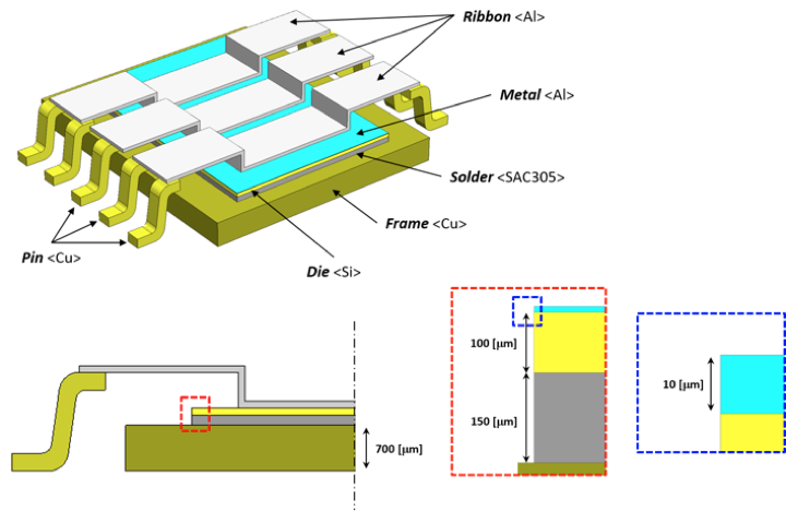
Base layout of the system for our model to app demonstration.
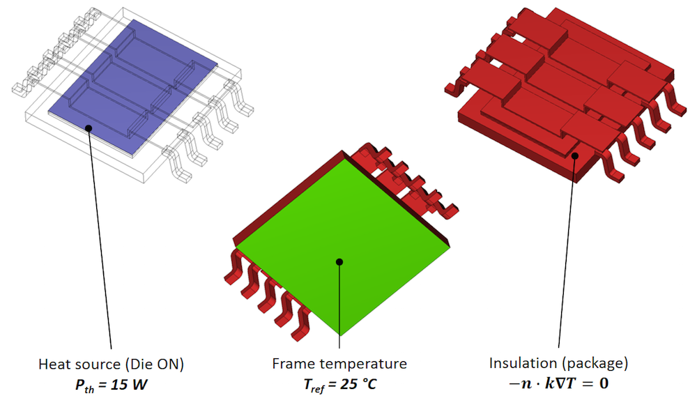
Source terms and boundary conditions applied in the embedded model.
When designing the app, we leveraged a number of functionalities within the Application Builder: the Action Button, Input Field, Combo Box, Graphic, and Data Display.
In our app, we labeled the action buttons as the following: Build, Mesh, Run, Reset data, Report, Layout, and Contact us. What, you might ask, is the purpose of each of these buttons? Let’s take a look:
- Build: Show the actual geometry in the graphics window after applying the solder thickness to the related input field
- Mesh: Generate the tetrahedral elements mesh
- Run: Launch the simulation
- Reset data: Return to the default settings
- Report: Create a COMSOL report
- Layout: Show the graphical contents presented in the above figure of the base layout
- Contact us: Display the contact information for BE CAE & Test
Users can manually introduce geometrical and functional parameters within the model via the app’s input fields. With the flexible nature of simulation apps, the parameters that are included in the app can be tailored to specific design needs. In this case, app users can modify the thickness of the solder layer and the dissipated thermal power.
Within our app, we implemented two combo boxes in order to choose the constitutive material for the solder layer and die. As the figure below illustrates, the material choice was added to the embedded model via a global materials definition and a material link. Each material is indexed with a string in which the global variables are defined, and an initial value and a choice list are both associated with the global variables. The value of the global variable, which app users can modify, is controlled by an interactive combo box. When the value is changed, the local method implemented in the Application Builder permits changes to the materials in the underlying model.
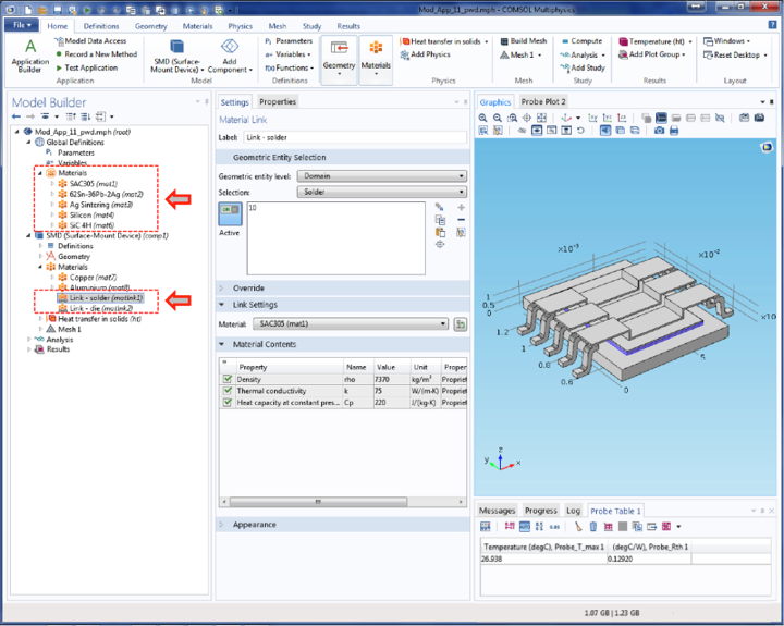
The global materials and local link enable users to change constitutive materials.
Further, we conceived data display objects to show the outputs of interest for a typical thermal-electronic device application, that is, the maximum junction temperature, Tjc(MAX), and the junction-to-case thermal resistance, Rth-jc, of the SMD. Meeting this goal involved using a standard probe that returned the output for the maximum value of the temperature evaluated over all domains. We also defined a second probe, assuming a global variable value for the junction-to-case thermal resistance. The value of the second probe is dependent on the value of the first probe, as the following figure indicates.
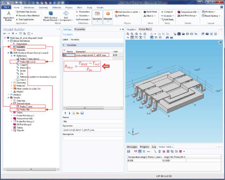
The global variable and probes are used to allow evaluation of the junction-to-case thermal resistance.
The app appears graphically, as it does in the earlier figure of the base layout. While running the app, the main graphics window changes to correlate with the different steps. Depending on the specific step, the window shows the actual geometry of the SMD, the finalized mesh, and the computed thermal distribution.
Now the app is ready to be run. When doing so, app users can evaluate many important thermal elements within the electronic device’s design:
- Thermal distribution within the device
- The maximum temperature over the whole device
- The junction-to-case thermal resistance as a function of solder thickness and dissipated power
- The constitutive material of the solder and the die
Building a Stronger, More Integrated Relationship with Customers
From our own experience with building and sharing simulation apps, we have found that apps offer an innovative way of interacting with customers. Rather than simply sending simulation results to them, you can provide customers with a flexible tool that they can use to investigate the problem on their own — all while ensuring accuracy in their results. This not only allows them to obtain results more quickly, but it also gives simulation experts more time to work on adding complexity to the model behind the app versus running simulations.
“What happens in my system if…” is a question that the team at BE CAE & Test typically hears when first meeting with customers. Traditionally, our reply was something like this: “Let us build a reference model for your system and then carry out parametrical simulations. We will be able to give you useful predictions, which are an essential advantage to virtual prototyping.”
Now, with the use of simulation apps, we have a much simpler reply: “Let us provide you with a COMSOL app, and you will be able to check yourself.”
About the Guest Author
Giuseppe Petrone is a cofounder and the sole administrator of BE CAE & Test, a COMSOL Certified Consultant. He received his master’s degree in mechanical engineering from the University of Catania in Italy and later earned his PhD in energetic and process engineering from the Université of Paris-Est in France. Before starting at BE CAE & Test, Petrone devoted his time to academic research ventures, which included exploiting numerical methods in fluid dynamics and thermal analyses. He has been a user of COMSOL Multiphysics since 2005.


Comments (1)
Maxime BARRIERE
July 30, 2018Dear friend,
Is it possible to share your application?
It looks nice and very functionnal.
Thanks.
Regards.
Maxime.