
Version 6.4 of the COMSOL Multiphysics® software expands the Surface-to-Surface Radiation capabilities of the Heat Transfer Module to include specular refraction (in addition to specular reflection) when using the Ray Shooting approach. This is particularly useful for solving radiative heat transfer problems involving collimated sources, such as due to solar radiation or laser light sources. Let’s take an in-depth look at these capabilities and the related features within the software.
Background: Refracted Light and Modeling Refraction
To begin, let’s look at a setup that you’ve likely seen in a museum: collimated light interacting with differently shaped clear glass pieces and curved mirrors sitting on a tabletop. The glass has a higher refractive index than the air so light rays passing through the boundaries of these parts deflect according to Snell’s law, and the intensity of the reflected and refracted radiation is given by the Fresnel equations. When the light is incident on the mirrored surfaces, it experiences specular reflection. As the light refracts through the glass elements, it also illuminates the tabletop — especially as the light is focused.
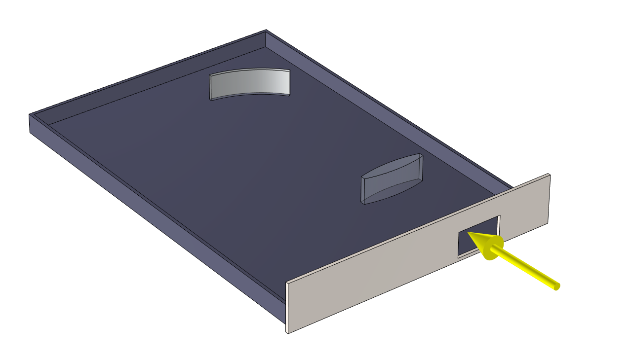 Two optical elements, a convex lens and a curved mirror, are on a table. A collimated light source at a shallow angle illuminates the table and optical elements through the opening at one side.
Let us say that we are interested in computing the temperature distribution across the surface of the table due to this incident light. Conceptually speaking, there are two parts to this modeling problem:
- Computing the incident irradiation
- Computing the temperature rise and the radiation between all emitting and absorbing surfaces
We separate them in this way because the incident irradiation is unaffected by the solution. That is, we assume that the source (the faraway Sun, or a laser light source) will not be affected by the temperature of the tabletop.
Furthermore, it is almost always a characteristic of these types of problems that the external sources, the Sun or the laser, radiate at wavelengths that are very different compared to the thermal radiation emanating from the heated parts. That is, the short-wavelength infrared or visible light is illuminating the structure and gets refracted through the glass optical elements without heating them directly, but the thermal radiation emitted from the other opaque objects is primarily long-wavelength. Since glass is typically opaque at these wavelengths, it will be directly heated by this longer wavelength thermal radiation. This means that we should use a so-called multiband model, where the thermal radiation is computed over several (or often just two) different wavelength bands.
We can set up and solve this type of problem using the Ray Shooting method, which uses a combination of the Forward Ray Shooting method for computing the thermal loading from external radiative sources and the Backward Ray Shooting method to compute the radiative loads on each surface from the surrounding surfaces. This method supports multiband radiation; can account for specular reflections; and, as of version 6.4, can handle specular refraction at dielectric interfaces. For conceptual simplicity, we will handle these two bands using two different Surface-to-Surface Radiation interfaces: one solely for computing the radiative heating from the external source and one for the reradiation around room temperature.
Let’s first look at some model results, and then go through the setup of such a model. As we can see from the plot below, the temperature is highest at two points on the table:
- Where the incident light is focused by the lens
- Where the light is focused by the mirror
Neither the lens nor the mirror gets very hot, even though there they are both being directly illuminated by the source.
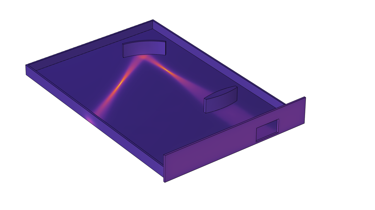 The temperature distribution due to the irradiation through the aperture. Hot spots occur due to the focusing from the lens and the mirror.
Setting Up the Model in COMSOL Multiphysics®
The setup of the model begins with the geometry, which consists of several objects representing a wooden tabletop with protruding sides, with a rectangular aperture cut into one side. Two glass objects are modeled: the convex lens and a curved part that is mirrored on the backside of the glass.
 Three physics interfaces are used within the model. Heat Transfer in Solids accounts for the conductive heat transfer, and the heat flux from the External Radiation Source is modeled as a heat load.
There are three physics interfaces in the model. First, the Heat Transfer in Solids solves for conduction within the table and glass materials and is solved in all domains. Second, a Surface-to-Surface Radiation interface is assigned to all boundaries exposed to air. This interface handles radiative heat transfer at medium to long IR wavelengths and is coupled with the Heat Transfer in Solids interface using the HT with Surface-to-Surface Radiation coupling. Keep in mind that glass, although transparent to our eyes, is actually a very good absorber (and hence a good emitter) at longer wavelengths.
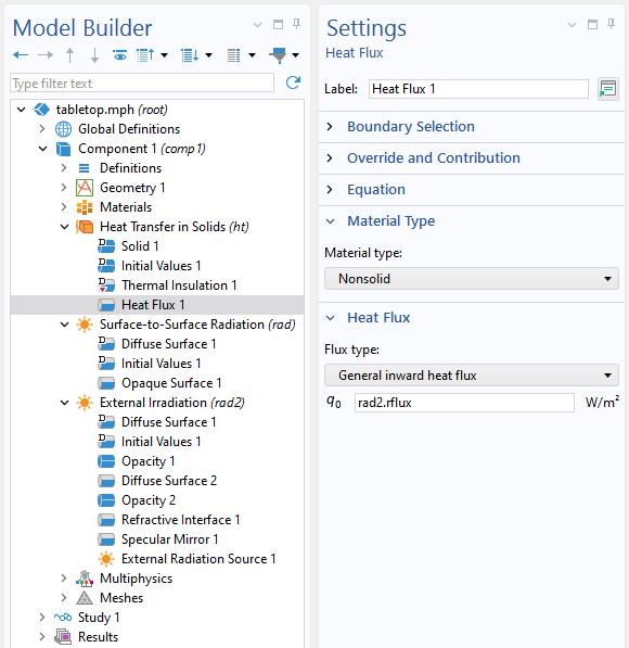
Lastly, there is another Surface-to-Surface Radiation interface. This is assigned to all exposed boundaries of the solid parts, as well as the boundary interface between the glass and the table. This interface is used solely to compute the incident heat flux from the external source, the Sun, under the assumption that this irradiation is at short wavelengths. The source itself is specified using the External Radiation Source feature, which specifies a flux and a direction. The computed deposited heat is then added as a boundary heat flux within the Heat Transfer in Solids interface.
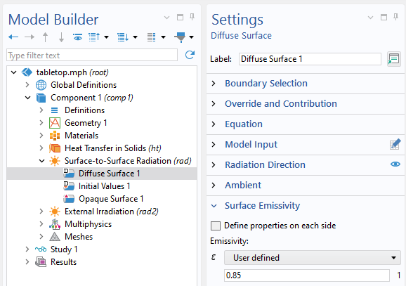 The tabletop is modeled as a set of diffuse surfaces.
Regarding the setup of the radiation model, most of the boundaries of the wood table are defined to be diffuse and highly absorptive, with an emissivity of 0.85. However, the surfaces of the aperture facing the incident solar radiation have an emissivity of 0.05, meaning that they are diffusely reflective to the incident light.
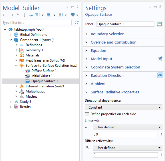 Modeling the surfaces of the glass parts using the Opaque Surface feature means that the surfaces act as specular reflectors and diffuse emitters.
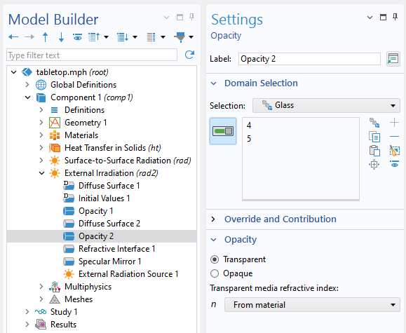 The Opacity feature is used in the interface that computes the external irradiation. It should be used in conjunction with the Refractive Interface feature on the surfaces of the refractive domains.
Within the IR-band radiation interface, the boundaries of the glass are modeled as Opaque Surfaces with an emissivity of 0.9 and a diffuse reflectivity of zero, meaning that they will have a specular reflectivity of 0.1. This is a good approximation of the thermal behavior of glass at longer wavelengths. On the other hand, within the interface that computes the solar irradiation, the glass domains are modeled as being perfectly transparent, but with a refractive index as defined by the Opacity feature. As of version 6.4, there is a Transparent media refractive index setting to define the refractive index of the domain. The surrounding void space, where there is no geometric model, has a refractive index of one by default. At the boundaries between the glass and air, the Refractive Interface boundary condition is applied to account for reflection and refraction as computed from the Fresnel equations.
Finally, the mirror on the back of the curved glass is modeled using the Specular Mirror feature in the interface that solves for the incident light. It is not modeled in the IR-band, since the mirror is not visible in that band.
When solving, it is possible to use adaptive mesh refinement to get a finer mesh of the heated zones. In addition to the temperature fields, additional useful plots include the external irradiation and the deposited heating from the external source.
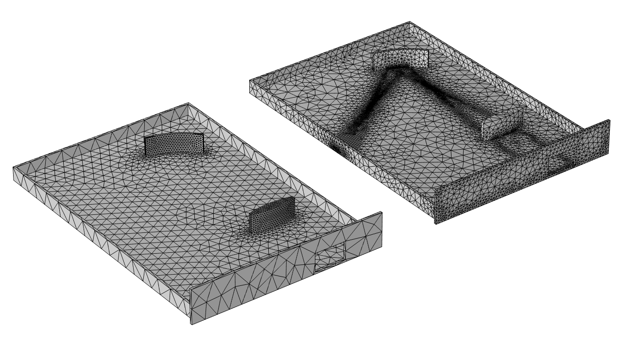 Illustration of adaptive mesh refinement around areas where the temperature variations are significant.
Closing Remarks
We’ve shown here how the capabilities of the Heat Transfer Module allow us to model radiation through refractive materials such as glass, which are treated as lossless around optical wavelengths. However, we also need to consider that glass is highly lossy at longer wavelengths. We’ve seen that one approach is to use two different Surface-to-Surface Radiation interfaces: one for the short-wavelength irradiation and one for the radiative heat transfer between surfaces around ambient temperatures. Both of these interfaces use the functionality of the Ray Shooting method.
It is also worth touching upon how this new functionality contrasts with the capabilities of the Ray Optics Module, which can trace rays from a source through an optical system and compute the deposited heat — not only on surfaces but also on domains. The Ray Shooting capabilities of the Heat Transfer Module implement the same underlying governing equations, Fresnel’s law of refraction and reflection, but do so in an averaged sense over all polarizations, while the Ray Optics Module will additionally compute and store the polarization of the rays. Ray Shooting is simplified in that it can only address domains of constant refractive index, without losses. The Ray Shooting method is much more computationally efficient than the Ray Tracing method, since it only computes the ray paths and doesn’t store them. As a practical consequence, this method can compute both incident radiation and the emitted radiation from the system itself, which is needed for high-fidelity thermal radiation modeling.
On the other hand, the Ray Tracing method of the Ray Optics Module launches rays only from specified sources. It computes and stores the rays, their intensity, polarization, power, and optical path length. These quantities are necessary for optical path-based computations, such as interference plots, spot diagrams, and aberration. Hence the Ray Optics Module is for users wanting to model the performance of an optical system.
It is possible to combine these approaches within a single model. You can use the Ray Shooting method to compute the radiative heating and temperature distribution over time, as well as the resultant structural deformation, and then use the Ray Optics Module to compute the optical performance. This workflow is particularly useful for those interested in structural-thermal-optical performance (STOP) modeling of devices, especially during transient states of operation.
Next Step
Interested in finding out more about capabilities in COMSOL Multiphysics® for modeling refraction? Contact Us!


Comments (3)
Ivar KJELBERG
December 23, 2025Hi Walter,
Nice model, would have loved to have these features some 10 years ago when I was very active in such STOP analysis.
One thing though : how are you sure that your second S2S External Radiation (rad2) physics is not doubling in the thermal radiation losses to the ambient environment ? And what value do you use in the (rad2) Temperature entry for its sub nodes ? And when will this model come in your application library ?
God Jul 😉
Sincerely Ivar
Walter Frei
December 23, 2025 COMSOL EmployeeHi Ivar,
Great question. There are a number of different approaches that one can take, and what I did in this example (which we make available via COMSOL Support) is to set the surface temperature of all faces, and the ambient temperature, to zero in the “external irradiation band” interface. So, the only heat source that is solved for (using the forward ray-shooting) is the incident light. There is also only a single multiphysics coupling. Regarding alternative approaches, there is also an example here:
https://www.comsol.com/model/thermal-radiation-with-refraction-144561
This contains a few different approaches, as there seems to be quite a bit of variation in what people would like to do here.
Happy Modeling!
Walter
Ivar KJELBERG
December 23, 2025Thank’s that improves my energy balance 🙂
I didn’t read this Tamb – Tinput trick in your text above.
Sincerely
Ivar