

The question of exactly how strong living bones are poses many important considerations for the medical industry. There is not currently a single-purpose device in the field to test bone strength. However, it is possible for researchers to get measurements of bone strength by modeling the entire makeup of the bone and using multiphysics simulation to perform stress and strain analyses. Simulating bone strength starts with a simple map of the external topology of the bone and then delves into its complex internal structure and composition.
FEM Is a Leg Up on Modeling Bone Strength
When researchers from the Universidad Tecnologica de Pereira, Colombia set out to determine the geometry, dimensions, and mechanical strength of a human femur, they employed the help of multiphysics simulation. Using COMSOL Multiphysics, the researchers experimented with different finite element models to determine the best way to design a model that most closely resembled a real bone. The results of their study were presented in the paper “Determination of Mechanic Resistance of Osseous Elements through Finite Element Modeling” at the COMSOL Conference 2013.
One of the modeling techniques that they explored was the implementation of isotropic materials, materials that respond the same way to forces applied in different directions, and anisotropic materials, those that have different physical properties depending on the direction of the applied force. Previous femur models assumed that the human femur was composed entirely of isotropic materials; however, these models failed to predict the correct fracture patterns that occur when a femur is exposed to high stress. By using both isotropic and anisotropic materials in their models, the researchers found the material composition that produced results that most closely matched data from experiments done on real human femurs.
Simulating Isotropic and Anisotropic Materials in a Femur
The researchers began by scanning a human femur using a three-dimensional laser scanner, and then using this information, they constructed a 3D finite element model. This gave them the external geometry of the bone; however, in order to determine the internal composition of various tissues, they consulted previous studies on bone strength and tissue composition.
A femur is made up of several sections: the trabecular bone, cortical bone, and medullary canal (shown below). The cortical bone is a type of osseous tissue that is very compact and that provides support, protection for organs, levers for mobility, and the ability to exchange chemical elements. Trabecular bone is spongy and closer to the center, and the medullary canal is the vessel where bone marrow is stored. The material composition of a bone can be determined using a type of radiography called dual-energy X-ray absorptiometry (DXA) that works to measure bone mineral density. Medical professionals aim two X-ray beams with varying energy levels at the bone tissue, then they subtract out the absorption level to get a reading of the bone mineral density. In addition, the experiments the researchers consulted used quantitative computed tomography (QCT); this is a technique for displaying an X-ray or ultrasound cross-section.
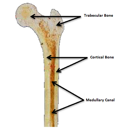
Internal structure of the human femur. Image courtesy of
E. Isaza, L. García, and E. Salazar and adapted from their paper.
The researchers modeled the head of the femur, as a generalized isotropic and anisotropic model. The trabecular and cortical bones were then simulated as either an anisotropic material or isotropic material in multiple different simulations that tested the material properties taken from previous experimental studies.
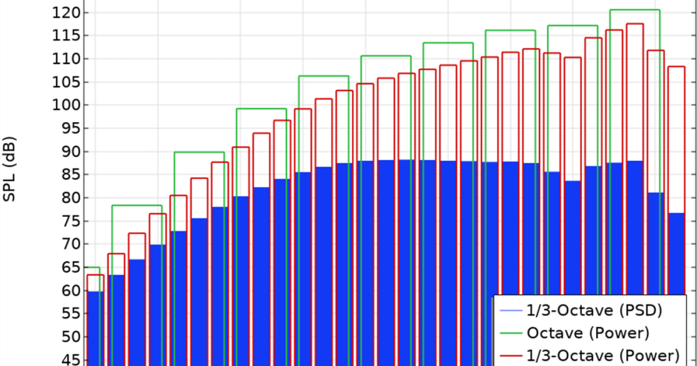
These models where then compared to experimental results (“Femoral strength is better predicted by finite element models than QCT and DXA.“, Cody et. al.) to determine which material properties most closely predicted the fracture load of that of a real bone. Their results are presented in the graph below:
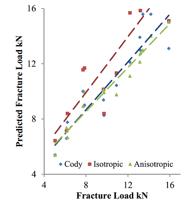
As the graph shows, the anisotropic materials more closely matched the data from the physical experiment. By simulating and measuring the stress patterns in both the anisotropic and isotropic models, the researchers were able to test the validity of this model as it corresponds to known stress patterns. The model below depicts the different stress distributions in the femoral head of the femur in the anisotropic and isotropic models, where the anisotropic model demonstrates a more accurate depiction of the mechanical resistance. Analyses such as these could potentially help to understand and predict the fracture patterns in low density bones.
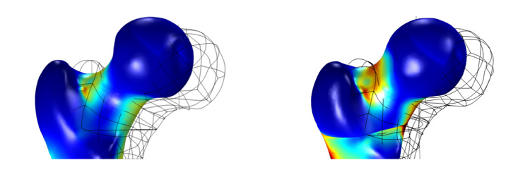
Stress in the femur head in an isotropic model (left). Stress in the femur head in an anisotropic model (right).
Both isotropic and anisotropic materials can be modeled in COMSOL, allowing for the easy implementation of multiple models to test different material compositions. This data could help individual patients lower their risk of disease, weakness, and vulnerability in bones. The large-scale impact could be improved medicine and treatment and a better understanding of the makeup of one of our most important structural systems.
Further Reading
- Check out the full paper “Determination of Mechanic Resistance of Osseous Elements through Finite Element Modeling” that was presented at the COMSOL Conference 2013.

Comments (0)