Aside from the winding type, concentrated or distributed, the logic behind the design of electrical machines is relatively similar, as it’s based on their phasor diagrams. Using an induction motor benchmark model with a concentrated winding, we’ll show you how to create selections in the COMSOL Multiphysics® software to streamline the analysis of your winding design. We’ll then demonstrate how to further advance your simulation studies by automating these processes with the Application Builder.
Our Induction Motor Example Model
The operating modes and types of electrical machines are defined by the way that their windings are connected. Their fundamental principle of operation is based on the voltages and currents flowing through these windings. Independent of the type of machine, the windings can be categorized as concentrated or distributed, with further subcategories such as fractional and integral also applied.
For concentrated windings, as the name suggests, each pole in the machine will have a set of conductors passing through the same slot. On the other hand, for distributed windings, the number of slots will be greater than the number of poles, so the conductors of each pole will be distributed among the number of slots. The benefits and differences of using concentrated windings versus distributed windings are outside of the scope of this blog post.
Our induction motor model was built using a pole pitch of 60°. This means that there is 60° of separation from the bottom of one stator slot to another. To create some uniform flux density lines and ensure induction on the steel rotor to produce motion, we need to make sure that there is some separation between each stator slot. In many rotor topologies, this gap is filled with the stator tooth. However, in this example, we have selected 15° of air gap, which means that each stator slot will cover 45° of the full 60° needed.
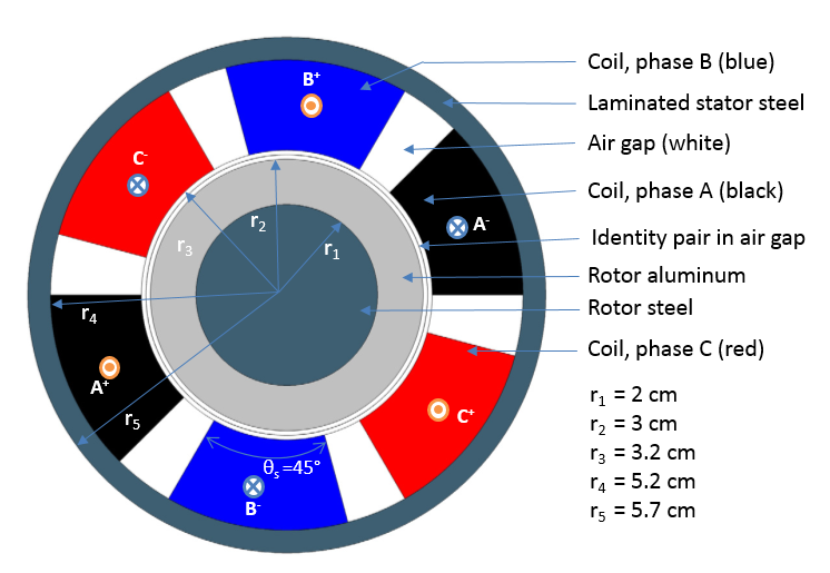
Three-phase induction motor schematic depicting the dimensions and phase configurations of the original model.
At this point, what we have described might sound complicated, but it is actually quite simple. As we mentioned earlier, the design of windings in electrical machines depends on their voltage phasor diagrams. In the figure below, the blue lines represent the phases, while the orange lines represent their negative counterparts.
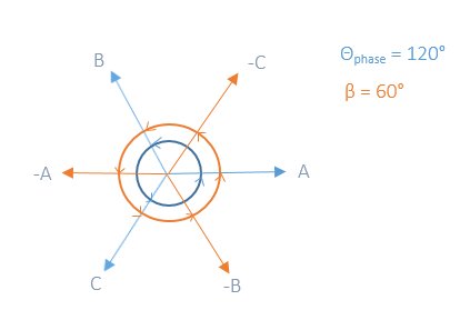
Three-phase phasor diagram.
The induction motor used for this example is a three-phase, two-pole machine, and it can be described exactly by the phasor diagram, where 60° defines the pole pitch in the stator. The only challenge here is that these angles of separation between each stator only work in the two-pole case. We need to create a relationship between the electrical angles shown in the phasor diagram, which describe the circular motion of the rotor, and the actual mechanical angle, which describes the physical location of each stator slot. The electrical angle is represented by the following equation:
Creating Selections in COMSOL Multiphysics®
Under the Definitions node, we can create selections, that is, group geometrical entities such as domains, boundaries, edges, and points. For the two-pole machine, there are two points of interest: identifying the stator slot corresponding to each phase and identifying the direction of the current (inward or outward). Note that while there are multiple ways to perform the same operation, this specific case serves as an example of how selections can be used in a model.
In the figure below, we have parameterized the ball selection in such a way that it is possible for us to always select the midpoint of each stator slot. As mentioned earlier, coil pitch is 45º and since we are working with a circular geometry, it is easy to parameterize the x– and y-coordinates to follow each coil location around the geometry:

Creating a parameterized ball selection in COMSOL Multiphysics.
Take a look at the screenshot shown above. Ball 1 represents phase –A and Ball 2 represents phase A. These elements have been collected under a single selection via the Union selection feature. This allows us to easily call them from the physics interface under each Coil feature.

Linking Coil 1: Phase A to the Union 1 selection and the Reversed Current Direction to the Ball 1 selection.
The highlighted boxes in the above screenshot show that the physics node can be linked to the domain selection. Here, the green box represents the Union node and the blue box represents Ball 1. Such linking is necessary to indicate where the current direction is reversed.
The order of the phases will determine the direction in which the rotor moves. We will therefore use the same sequence as the original example, starting from phase –A. Now let’s consider a four-pole machine and describe the electrical angle and mechanical angle as well as the phase and direction of the current. The following table provides an overview of these elements.
| Phase | -A | B | -C | A | -B | C | -A | B | -C | A | -B | C | Current Direction |
|
|
|
|
|
|
|
|
|
|
|
|
θelectrical | 0 | 60 | 120 | 180 | 240 | 300 | 360 | 420 | 480 | 540 | 600 | 660 | θmechanical | 0 | 30 | 60 | 90 | 120 | 150 | 180 | 210 | 240 | 270 | 300 | 330 |
|---|
Relationship between the phase, current direction, electrical angle, and mechanical angle for a four-pole machine.
If done manually, this task can become rather tedious. To perform the same operation, we would need to create twelve ball selections, group them into three unions, and then identify every reversed current direction. Now imagine doing this for an eight- or a ten-pole machine and having to manually change each selection for every winding design. As we’ll demonstrate next, the Application Builder becomes quite handy in such situations.
Using Methods to Create Dynamic Selections in the Application Builder
With Application Builder, you can develop a customized user interface that is tailored to your specific needs. Here, we have parameterized our model in order to create a function that depends on the stator pole pitch and the mechanical angle and can be used to model an induction three-phase machine for multiple poles. As noted earlier, there are many ways to perform such an operation, but our goal is to showcase the capabilities and advantages of using selections and the Application Builder to do so.
The functions entered as x and y positions within the ball selections can be described by the following expressions, respectively:
where θs is the coil pitch and n is just an integer ranging from zero to the total number of coils in the model.
Since we are working with three phases and two current directions, we can easily use the mod function (%) to identify the two interesting attributes of each coil: the phase and current direction. If we start counting coils from phase –A until all of the mechanical angles are covered for each coil slot, we would end up with something similar to the table below for the four-pole case.
| Phase | -A | B | -C | A | -B | C | -A | B | -C | A | -B | C |
Coil Number (i) |
0 | 1 | 2 | 3 | 4 | 5 | 6 | 7 | 8 | 9 | 10 | 11 | i%3 | 0 | 1 | 2 | 0 | 1 | 2 | 0 | 1 | 2 | 0 | 1 | 2 | i%2 | 0 | 1 | 0 | 1 | 0 | 1 | 0 | 1 | 0 | 1 | 0 | 1 |
|---|
Description of the algorithm used to identify each phase and when to reverse the current direction.
Here, a coil number (i) of 0 represents phase –A, a coil number of 1 represents phase B, and so on. Using i%3, we can easily identify phase A as 0, phase B as 1, and phase C as 2. Further, for each phase starting from phase –A, we can see that the negative current is identified as 1, whereas the positive side of the current is identified as 0.
To see how this works as described in the previous table, let’s look at a section of the code created in the Method Editor of the Application Builder.
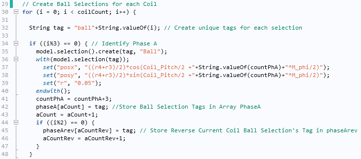
Generating automated ball selections using the Method Editor for each coil.
The above image only shows how to create the selections for phase A. Here, we use three counters: i counts from 0 until the last coil (11 in the four-pole case). If i%3 is true, then we can say it is phase A, and we will store those selections in array phaseA. We’ll then need to check for the current direction. If i%2 is 0, then the direction of the current is considered negative, and we will store those selections in another array called phaseArev.
So far we have created ball selections, but we still need to create the unions. This operation is rather easy to perform as we will always have six unions in our case: phase A, phase B, and phase C, along with the three unions corresponding to the reversed current direction.
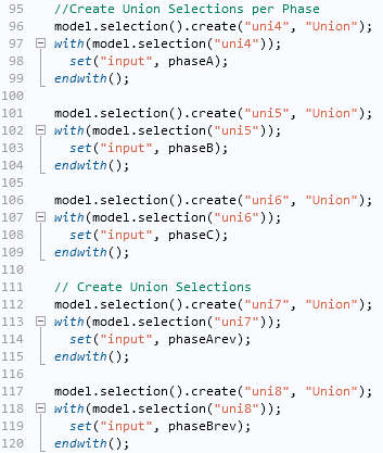
Creating union selections using the Method Editor for each phase.
In the same fashion, we’ll need to make sure that each union is assigned to its corresponding physics interface.
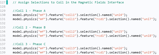
Linking the coils to the union selections and the reversed current direction to the ball selections using the Method Editor.
We have now finalized the creation of selections that will depend on the number of poles entered by users of the app. With more time and additional creativity, you could further extend the functionality of this app via the Form Editor. This tool gives you the ability to design an app that enables users to, for instance, assign material properties, account for time dependency of the solution (transient or harmonic), and even automate postprocessing. Such features are highlighted in the screenshot below.

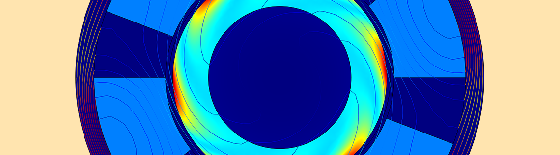
A simulation app based on the original induction motor model. This app creates and displays selections based on the relationship between the electrical and mechanical angles.
Learn More About Using Selections and Automating Processes with the Application Builder
- Read about how different types of selections can streamline your simulation workflow
- Find out how you can use the Application Builder to automate model preprocessing
- Download the related simulation app: Winding Designer for Electrical Machines


Comments (0)