Ultra-precise optical components require blemish-free surfaces that often cannot be achieved by the machining processes that grind these components. Fluid jet polishing (FJP) is a new technology being developed by Zeeko Ltd to replace the hand polishing that was often required. With the help of COMSOL, Zeeko was able to create a product that polishes the optical components in only ten minutes instead of an entire day, and without waveforms.
Jet Polishing: a More Efficient Method for Optical Surface Smoothing
What do space telescopes, orthopedic joints, and digital cameras have in common? They are all products requiring a number of precision processes including milling, grinding, polishing, and finishing. These products must have a completely smooth surface, with blemishes of only a few nanometers in some cases, being acceptable. Up until now, a laborious process of finishing by hand has been required. Zeeko Ltd is a company looking to improve this process, using fluid jet polishing. During FJP, a mixture of water and abrasive particles, called a slurry, is pumped through a nozzle onto a work piece. The technology has many advantages, but could not be fully utilized because of one significant factor: FJP imposed a finish with significant waveform patterns that diminished the optical devices’ operability. The system needed to cut the size of these patterns from more than 10 nm to as close to 1 nm as possible.
Multiphase Modeling
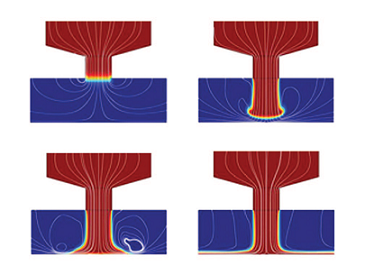
To solve the problem, Dr. Anthony Beaucamp, of Zeeko, turned to COMSOL Multiphysics. He wanted to simulate the fluid-air interface and trace the individual abrasive particles. First, using the k-ω turbulent flow model together with level-set and phase-field methods in the CFD Module, he produced a series of snapshots depicting the slurry flowing from the nozzle, impacting the surface and then flowing away (figure below).

Snapshots of simulation: slurry (red), air (blue), and streamlines (white).
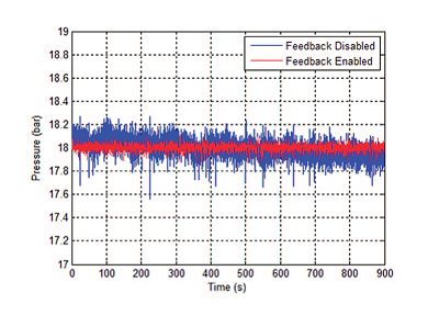
After that, he used the Particle Tracing Module to consider the forces, such as drag, on the individual particles in the slurry. Using the results from these two models, Dr. Beaucamp simulated the effects that a feed-in pump imposes on the system. It is the small variations in fluid pressure arising from the pump that produces the waviness. He then included a feedback control loop, and was able to add pressure stability to the system, see the difference between the blue and the red lines in the below diagram.

Pressure stability with (red curve) and without (blue curve) a feedback loop.
Multiphysics Modeling Assists Zeeko in Saving Manufacturing Companies Time
The model results were used to compute optimal conditions for the slurry delivery system. Results showed that the waviness dropped from 12.5 nm to 1.2 nm, indicating success and the go-ahead to develop the equipment. Manufacturing companies are now using Zeeko technology to finish their products, a process that takes ten minutes, instead of a full day.
Get the full story in COMSOL News 2012.


Comments (0)