
We have the pleasure of introducing guest blogger, Mark Yeoman of Continuum Blue, who showcases what they can do for clients in the electromechanical brake field.
Electromechanical brakes come in various designs, including single to multiple friction-face systems, power-off and power-on types, and those that include permanent magnets. With so many options, how do engineers make the right design choices for their application? With COMSOL Multiphysics, this can easily be done. Here, I will show you how.
Electromechanical Brake Design
So, what are electromechanical brakes anyway? In principle, they are brakes that use electromagnetic fields to retard, or stop, kinetic or mechanical motion. When it comes to their design, there are countless shapes and options available. Some of these include common single- or multiple-friction discs types, ones that use internal magnetic flux to produce a retarding force (hysteresis brakes), or magnetic-particle brakes.
Not only do we have various methods of electromechanical braking, but where they are used can have an influence on the size, braking torques, and response times required.
Design Challenges
Electromechanical brake applications range from locomotive and automotive vehicles to electric motors and robotics. These diverse applications, combined with the ever-increasing need to move to sustainable energy sources and materials, force engineers to design better, energy-efficient electrical systems (such systems could reduce the demand on power sources, like batteries). To top it all off, engineers are also tasked to design electromechanical brakes that are better than what currently exists on the market. It appears as if, we engineers, don’t have it easy when designing electromechanical brakes!
A Solution
Don’t worry. It’s not all doom and gloom as there is “light at the end of the tunnel”. I am about to show you how we can help ease the design process by demonstrating how the COMSOL software can be used to model the complex physics of an electromechanical brake design. Additionally, I will demonstrate how engineers can use the software to easily assess and quantify a design’s performance.
An Example
So, let’s get back to electromechanical brake designs. Single- or multiple-friction discs systems are the most common. They can be configured as power-on, where if the electrical power is on, the brake becomes active, or as power-off, where the brake is active when the electrical power is either accidentally lost or intentionally disconnected.
The image below illustrates two sectional schematics of typical power-on and power-off brake systems. Both use single-face friction plates to produce the braking action.
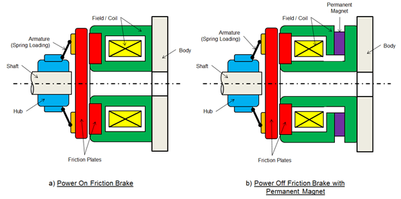
Schematic of a power-on (a) and a power-off (b) single-friction disc type electromechanical brake system.
Both types of brakes use spring armatures, which in the case of the power-on design, keeps the friction pressure plate in its neutral position in active state. While on the power-off design, the spring pushes the friction plate against the friction disc. In addition to the applied armature spring force, the power-off design has a permanent magnet, which aids in the frictional force applied across the friction disc.
COMSOL Multiphysics Model of a Power-off Brake
To make this blog post a little more interesting, I’ll be focusing on the analysis of the power-off type friction brake, with both an armature spring and a permanent magnet, forced across the friction disc (similar to that illustrated above). However, in order to simplify the analysis of the brake, the shaft and hub will be ignored. Only the rotational motions and spring forces from the armature spring, applied to the armature, will be assessed. Below, is a geometric representation of the system, created with the COMSOL software.
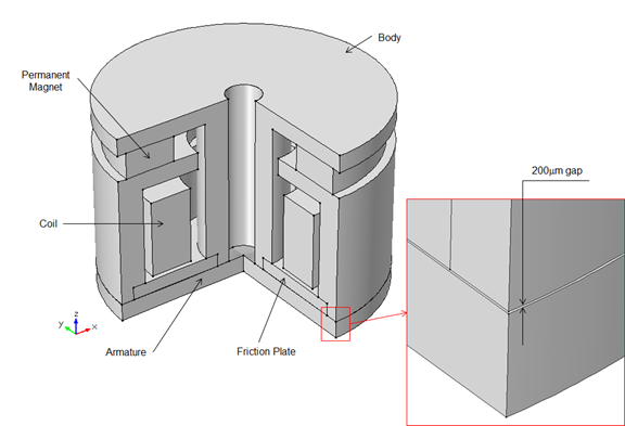
A COMSOL Multiphysics geometric model representation of a power-off brake with a permanent magnet.
With COMSOL Multiphysics, it is not only possible to model the electromagnetic forces of the permanent magnet and electromagnetic coil, but also the coupled effects of the structural motion, contact pressure, frictional forces, and the thermal response of the brake over time. Making use of the AC/DC, Structural Mechanics, and Heat Transfer modules, we are able to fully describe and simulate the real-time effects of this electromechanical brake. In this example, I’ve coupled the AC/DC and structural mechanics physics only.
A summary of the brake details and materials I’ve implemented are given in the table, below.
| Description | Details | |
|---|---|---|
| Outer Diameter of Brake | 160 mm | |
| Armature Spring Constant | 1×10⁶ N/m | |
| Permanent Magnet Magnetic Flux Density | 0.35 T | |
| Materials | ||
| Body | Stainless Steel 316 | |
| Armature | Soft Iron with losses | |
| Casing & Friction Plate | Iron | |
| Coil Specifications | ||
| Wire Diameter | 0.75 mm | |
| Coil Turns | 250 | |
Due to the force of the armature spring, when the coil is deactivated or powered off, the armature plate will initially be displaced by 200 µm and force it into contact with the friction plate. Due to the magnetic forces from the permanent magnet, an additional force is applied across the armature and friction plate. Thus, when the brake is powered and the voltage across the coil is increased, the brake, which is initially engaged, will become disengaged at a specific voltage. This will cause the brake to release and allow the armature to rotate. Further increasing the voltage across the coil will then re-engage the brake, above a higher specific voltage.
From the model, we’re going to look at the following performance factors as the coil voltage is increased: maximum frictional contact pressure across the brake pad; the points at which the brake becomes disengaged and re-engaged; the displacement and forces acting on the armature, due to both the spring and magnetic field; and the stresses in the armature.
Analysis Results
The model’s coil voltage was increased from 0 to 40 V in steps of 0.5 V to assess its response. From the solved model, the following performance data was obtained and graphically presented, below.
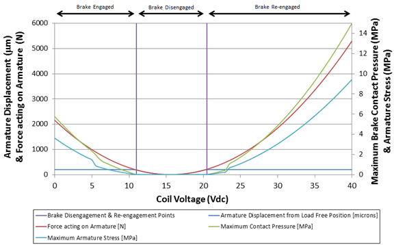
Graphical representation of analysis results obtained from the COMSOL Multiphysics model.
As can be seen from the graphical data, the electromechanical forces acting on the armature are initially at 2151 N. These forces are gradually reduced to 0.2 N, and then back up to 5300 N, as the voltage is increased. This force results in similar trends in the maximum contact pressure and stresses observed in the armature. Additionally, we can assess the resulting displacement and find out when the brake becomes disengaged.
Also seen in the graph, the brake is initially engaged with the armature displacement of 200.37 µm. It then becomes disengaged at 11 V, when the armature displacement goes below 200 µm, and the contact pressure becomes 0 MPa. At 20.5 V, the brake becomes re-engaged.
Moreover, we are able to assess the magnetic flux density change and the contact pressure profile across the armature plate. The contact pressure profile is important; designers need to ensure they have an even contact pressure distribution across the friction plates (not only does this increase the braking torque, but also reduces the possibility of excessively wearing certain regions on the friction plate). This would result in the need to continuously replace the brake pads during the brake’s life. Designers can also use this data to find out the standing torque values of the brake.
Below is an animation of the transformation in magnetic flux density (streamlines) and contact pressure across the armature plate, with change in coil voltage.
Animation of electromechanical brake response, including magnetic flux density (streamlines) and contact pressure on the armature friction plate.
From this model, engineers can easily assess brake design. With the use of parametric sweeps or the Optimization Module, engineers can also vary the geometric, material properties, and coil variables of the design to find the optimal electromechanical performance. Doing this reduces the size, weight, and power consumption of the brake, all while giving superior performance at reduced costs.
Although I did not couple the thermal response of the brake in this model, it is important to know that as the voltage is applied, and the brake disengages slightly, heat will be generated by the coil and from friction as the armature starts to turn (depending on the torque applied). Thermal effects will change the response of the brake, so it is important to assess the magnetic, electromagnetic, structural, and thermal responses together. By adding joule and induction heating to the COMSOL Multiphysics model, one is also able to assess the change in the brake response as it heats up and under various duty cycles.
About the Guest Author


Comments (0)