Polarization Settings for Periodic Ports
It is important to understand how to specify the polarization of the E-field when modeling periodic structures. Here, you will learn how to correctly set up the polarization (and angle of incidence) of an incident plane wave when using periodic ports. To do so, we will first demonstrate how to set up the periodic ports for s- and p-polarized incident waves, also known as the transverse electric (TE) and transverse magnetic (TM) polarizations, respectively. Then, we will consider the more advanced case of mixed s- and p-polarizations and verify our results by comparing them with the predictions of the Fresnel equations. We will then conclude with a brief discussion of elliptically polarized incident waves.
 A diagram showing s- and p-polarizations.
Setting Up Periodic Boundary Conditions
Automated Implementation
In version 6.3 of COMSOL Multiphysics®, the Periodic Structure feature enables quick and easy setup of models involving periodic boundary conditions. For the incident field polarization, we can directly select linear (S, P, or mixed); circular (right-handed or left-handed); or user-defined, as shown in the screenshot below.
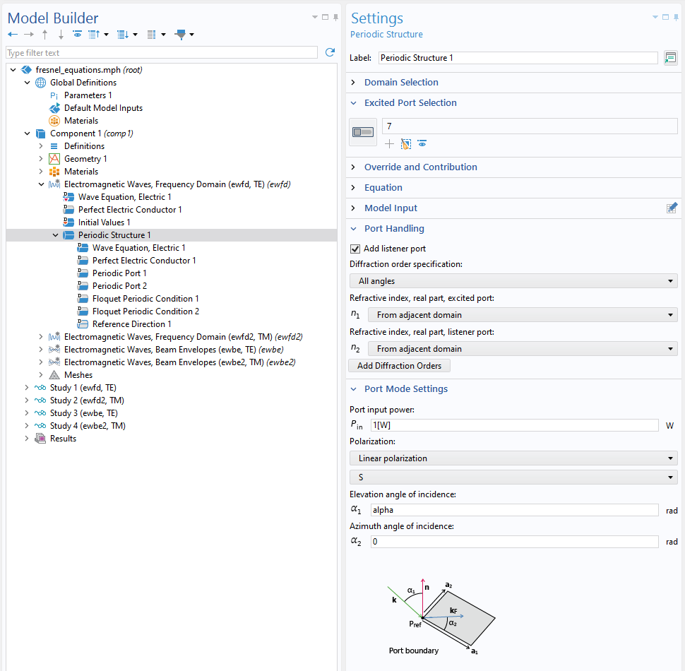 A close-up view of the Model Builder with the Periodic Structure node highlighted and the corresponding Settings window.
Polarization settings of the Periodic Structure node.
A close-up view of the Model Builder with the Periodic Structure node highlighted and the corresponding Settings window.
Polarization settings of the Periodic Structure node.
To gain a better understanding of how this works, let's take a look under the hood and explore how to manually specify the polarization.
Background and Manual Implementation
To demonstrate how to set up the polarization for periodic ports, we will use the Fresnel Equations (Wave Optics) tutorial model. The example models found in this section were created using the Electromagnetic Waves, Frequency Domain interface; however, the information here applies equally to the Electromagnetic Waves, Beam Envelopes interface.
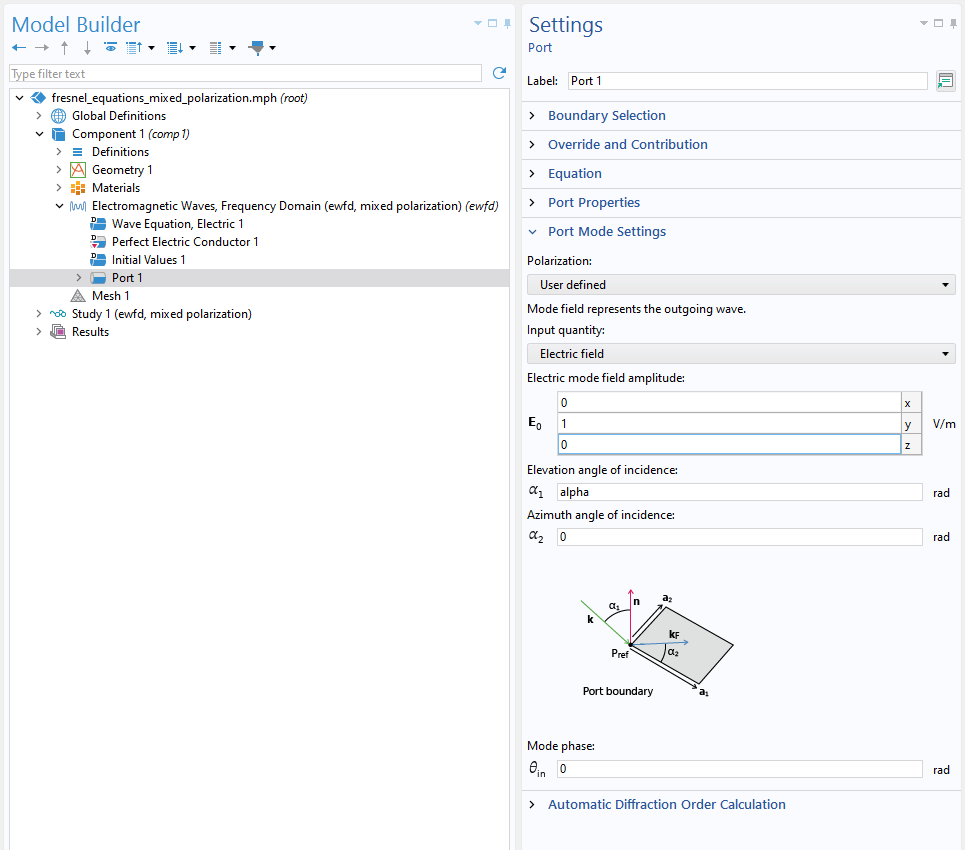 A close-up view of the Model Builder with the Port node highlighted and the corresponding Settings window.
Setting up an s-polarization periodic port boundary condition.
A close-up view of the Model Builder with the Port node highlighted and the corresponding Settings window.
Setting up an s-polarization periodic port boundary condition.
The orientation of the wave vector of the exciting field is specified by the elevation angle of incidence  and the azimuth angle of incidence
  . The quantity corresponds to the angle of incidence (0 for normal incidence and
  for grazing incidence), whereas specifies the plane of incidence (the plane spanned by the wave vector
  and the port boundary normal vector). At 0, the plane of incidence is the
  -plane. A value of would rotate the plane of incidence into the
  -plane. For simplicity, we will consider only incidence in the -plane, and will be denoted by
  .
.
The polarization of the exciting wave is determined by entering the electric mode field amplitude  (or magnetic mode field amplitude
  ) at the port boundary. With
  , setting parallel to the
  -axis corresponds to s-polarization. This is the simplest possible setting, since this will work for an arbitrary .
For p-polarization, the E-field will now be contained in the plane of incidence, but it has to remain orthogonal to , so the correct orientation will depend on . However, there is a shortcut for determining this. From Maxwell's equations, we know that and are orthogonal to each other and (for plane waves propagating in free space) , so for a p-polarized wave, will have identical orientation to of an s-polarized wave traveling in the same direction. Thus, to switch from s- to p-polarization in the above example, you can select Magnetic field instead of Electric field as the Input quantity setting.
For cases where the incident wave is in between s- and p-polarizations, the principle of linear superposition tells us that any arbitrary polarization can be decomposed into an s-component and a p-component. Before addressing this, we first need to understand an important convention related to the port mode settings in COMSOL Multiphysics®. At the top of the Port Mode Settings section, in the Settings window for the Port node, it states that "Mode field represents the outgoing wave." This means that the incoming wave must be specified as though it had reflected and is now traveling away from the model. Mathematically, this translates to changing the sign convention of  , the normal component of the wave vector. Since for the cases mentioned above, we were able to specify a field that was perpendicular to the plane of incidence, considering an outgoing wave instead of an incoming one made no difference in the field orientation. However, we will no longer be able to ignore this convention when dealing with mixed polarizations.
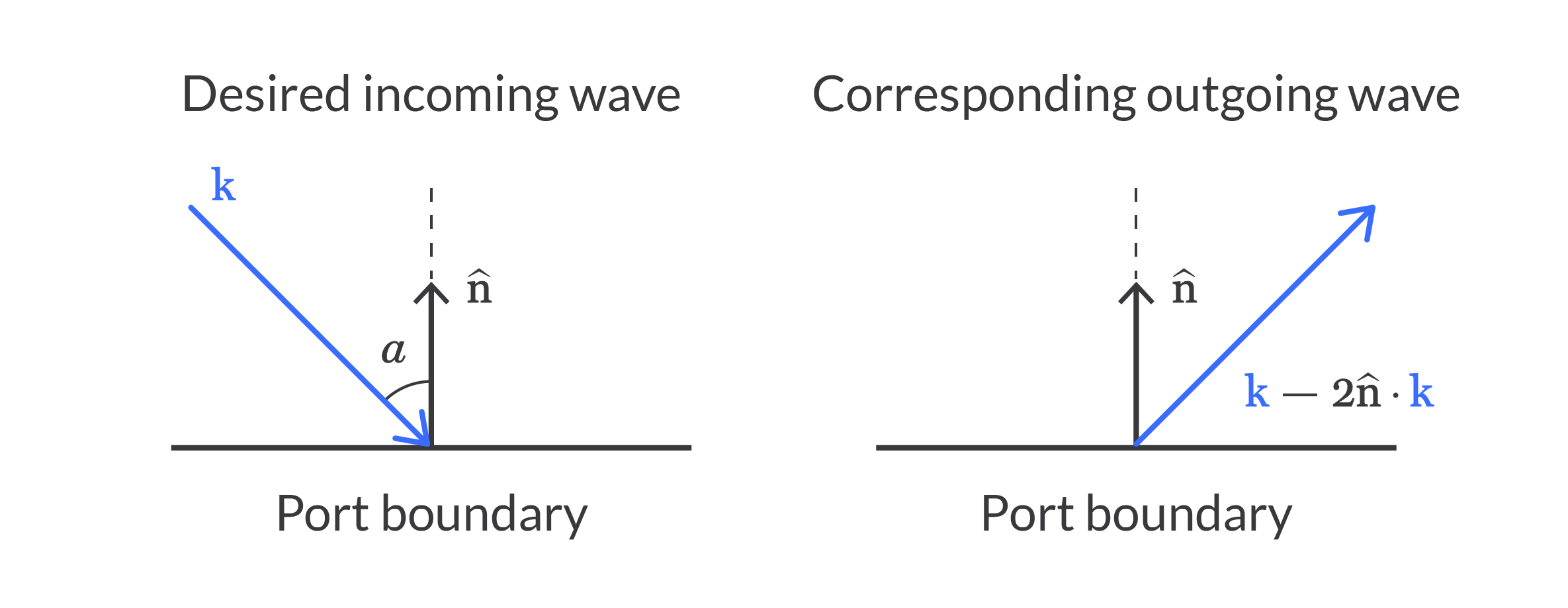 A diagram of the incoming and outcoming waves for mixed polarization.
Below, you can view the correct port mode settings for the case of incident wave with  , where
  and
and  are the vector amplitudes of the s- and p-polarized waves, respectively, and
  . On the incident side, the angle of incidence
 alpha can be used directly to specify the field orientation, but on the transmitted side, we need to use the angle of refraction as calculated from alpha using Snell's law (denoted bybeta below). An extra minus sign needs to be added to the z-component of the mode field at Port 1 to obtain the outgoing mode as described above. Note, however, that at Port 2, there is no incident field, and the transmitted wave will by default be outgoing, so there is no need for a sign convention change.
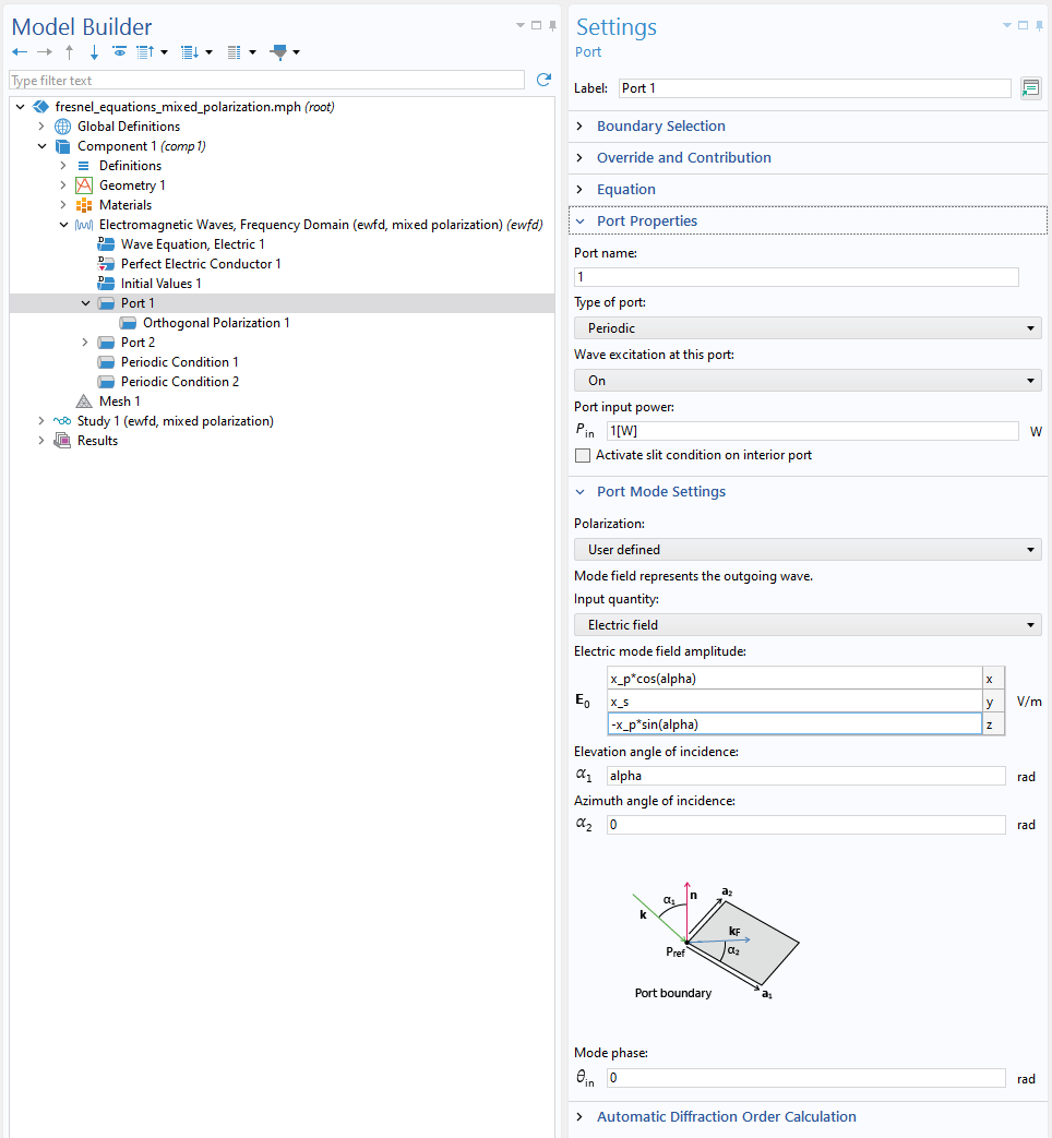 A close-up view of the Model Builder with the Port node highlighted and the corresponding Settings window.
 A close-up view of the Model Builder with the Port node highlighted and the corresponding Settings window.
There is one final factor to consider. The relative amounts of s- and p-polarizations change upon transmission and reflection due to the polarization-dependent reflectivity and transmissivity (see Fresnel's equations below). Thus, the polarization directions of the transmitted and reflected waves are different from each other and those of the incident wave. In COMSOL Multiphysics®, the Orthogonal Polarization subnode, under the Port node, enables us to conveniently account for mixed polarizations without the need to manually enter the Fresnel formulae. This feature essentially handles the change in the polarization direction by absorbing the "excess" component of s- or p-polarization. Adding this subnode generates the additional reflectance variable ewfd.Rorder_0_0_orth, which needs to be included in the total reflectance.
To ensure that the settings are correct, we can verify them by comparing the port reflectance and transmittance with Fresnel's equations. Again, by the principle of linear superposition, we have:


where,


As an example, the plot below shows good agreement with the analytical formula for  :
:
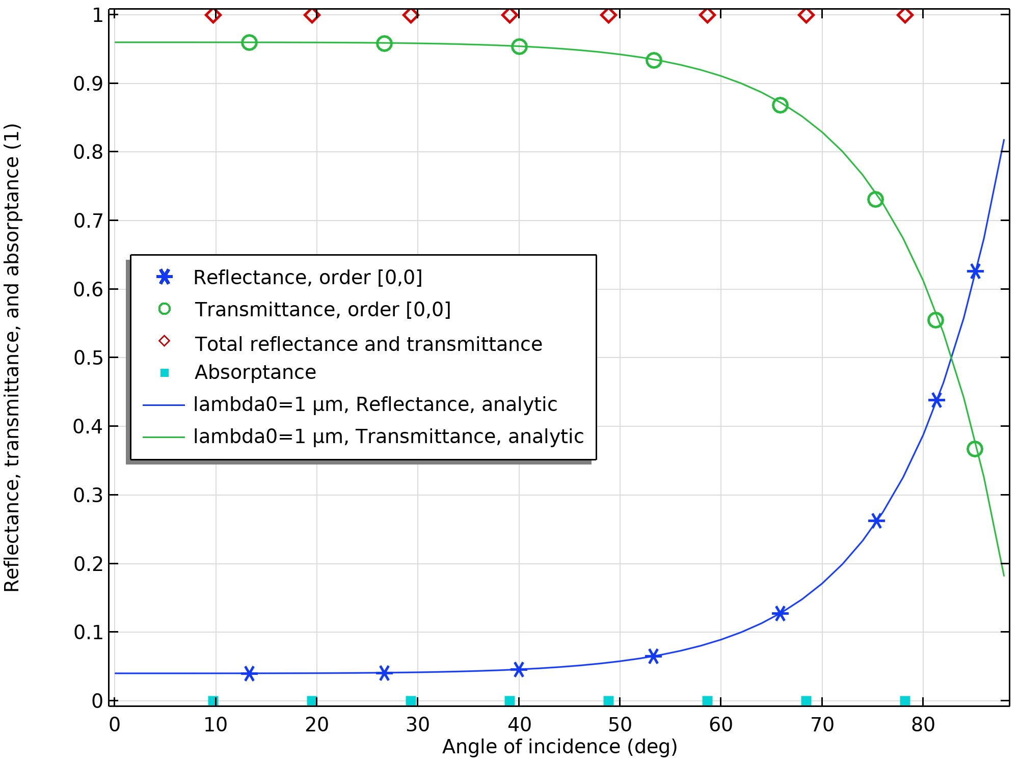 A plot showing that the reflectance and transmittance for TE incidence agree well with the analytical solutions.
In this article, we have considered only linear polarization. However, since elliptically polarized waves are superpositions of linearly polarized waves with different phases, we can set up circularly and elliptically polarized incident waves by letting and take complex values.
Further Learning
For information about the other settings for periodic ports, as well as the settings for the periodic boundary conditions, see the Wave Optics Module > User's Guide > Wave Optics Interfaces > The Electromagnetic Waves, Frequency Domain Interface > Port section of the COMSOL Documentation.
Submit feedback about this page or contact support here.