Preliminary Design of the New HI-LUMI LHC Beam Screen
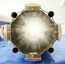
The high luminosity large hadron collider (HL-LHC) project aims at increasing the integrated luminosity by a factor of 10 from its original value (from 300 to 3000 fb-1) leading to the potential extension of scientific discoveries. To attain this goal, important upgrades will take place in the LHC by 2024 including the installation of new superconducting magnets in which new beam screens will be placed. The beam screen, shown in Figure 1, is inserted into the cold bore of superconducting quadrupoles a few tens of meters from the proton beam interaction points (ATLAS and CMS). It ensures the vacuum stability and shields the magnet cryogenic system from the beam induced heat loads through tungsten blocks connected to cooling capillaries via highly conductive thermal links.
The subject of this presentation concerns the thermal, magnetic, and mechanical behavior of the beam screen during a LHC worst-case scenario, namely, a magnet quench. In case of a quench, the beam screen has to guarantee its mechanical integrity to ensure vacuum and thermal stability. For this reason, a numerical model has been developed through COMSOL Multiphysics® software to analyze the induced currents due to the rapid magnetic field decay and, as a consequence, Lorentz forces and resistive heating losses. The Magnetic Fields, the Heat Transfer, and the Solid Mechanics physics interfaces have been coupled in a time dependent study.
The multiphysics nature of the phenomenon makes COMSOL an ideal platform to evaluate the response of the component undergoing a magnet quench. The assembly is modeled as a quarter to take advantage of the symmetry along two longitudinal planes slanted at 45° and 135°. Figure 2 shows the eddy currents flowing through the longitudinal surfaces of the screen generated as loops perpendicular to the four poles of the field. The induced Lorentz forces tend to expand the assembly along the vertical and horizontal directions, see Figure 3. Figure 4 shows the temperature distribution due to resistive losses; the average temperature increase is about 25 K while, locally, it can reach 150 K. The Lorentz forces are the cross-product of the magnetic field and the current according to the Maxwell equations.
The visualization of the current paths plays an important role in understanding the directions of such forces. They increase almost linearly up to 0.06 sec and decrease reaching negligible intensity at 0.2 seconds. The thermal link is subjected to a considerable von Mises stress and is then the most delicate part of the whole assembly. Several shapes and thicknesses are being investigated through COMSOL data.
It is important to point out that stress analyses are conservative since the temperature dependence of the electrical resistivity is not considered. Local temperature increases have been reduced by means of thermal analyses. It has been proved that by leaving a gap between the thermal link and the beam screen, the local temperature rise remains acceptable with no material properties compromised.
Download
- morrone_presentation.pdf - 3.43MB
- morrone_abstract.pdf - 0.74MB