Hydrodynamic Flow Focusing for Microfluidic Cell Sorting Chip
Hydrodynamic flow focusing is an important requirement of microfluidic cell sorting devices. It allows the cells to arrive sequentially at the sorting location making detection easier. The simplest flow focusing configuration uses a three input Y-shaped microchannel. The sample enters the device from the central inlet and is squeezed by two side streams containing buffer (called "sheath" flows). The final focused width of the sample stream is purely a function of the flow-rates of central and sheath flows.
Based on literature survey [1-3] and our microfabrication capabilities, the channel width was chosen to be 200μm in our device (Fig. 1). The side (sheath) channels meet the central channel at 60 degrees [4]. This is because an angle of 30 degrees leads to very low pinching. On the other hand, an angle of 90 degrees builds up extreme pressures, which may be detrimental for the cells. The channel height was chosen to be 30 μm.
The device geometry is simulated using the Microfluidics Module of COMSOL Multiphysics® software with 3D simulation. In the current work, we have reported both steady state and time dependent simulations. The next step is to specify inlet and outlet velocities. We do so in terms of the flow rates. All three inlet flow rates were set as 10μl/min. We chose the "no-slip" boundary condition. This boundary condition ensures that the fluid comes to rest at the channel walls. The next step is to create a mesh. We chose the "extremely fine" mesh option for better results. However, this kind of a mesh slows down the simulation.
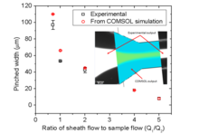
A C-shaped pressure profile is observed at the junction of three channels (Fig. 2b). The pressure is at maximum at the inlets and then gradually decreases as we travel along the channel. It appears that the velocity is maximum at the center of the channel. By varying the flow-rates different pinching widths were achieved. There is no theoretical limit to the pinching width; we found a practical lower limit to the pinched flow in simulations. This is because back flow happens from the side channels into main channel. In our simulations, the minimum width of 8µm was observed when the ratio of the sheath flow to the sample flow was 5.5.
The nature of the output barely changes even when the flow rates are increased or decreased, as long as all three flow rates are the same. When the sample flow rate is increased compared to the sheath flow, a bulge is produced at the junction. It keeps on increasing till the bulge starts touching the walls. As soon as it touches the walls in the flow-focusing zone, back-flow starts. COMSOL Multiphysics® simulations were experimentally verified over the flow range 1-1000μl/min. The simulation output is cropped, rotated and its edges are matched with the experimental output figure. The simulation results match very well with what we get experimentally (Fig. 4).
Download
- mehendale_presentation.pdf - 2.62MB
- mehendale_poster.pdf - 0.83MB
- mehendale_paper.pdf - 3.37MB
- mehendale_abstract.pdf - 0.42MB