
STEP Fusion and Demcon Multiphysics Design a High-Performance Tokamak
A STEP in the Right Direction: Modeling AC Losses in a Tokamak Design
STEP Fusion, led by UK Fusion Energy Ltd., worked with Demcon Multiphysics to calculate expected AC losses in the fusion system for the Spherical Tokamak for Energy Production program.
By Joseph Carew
July 2026
Each passing year brings the world closer to unlocking grid-scale fusion energy. Organizations are funneling significant resources into fusion reactor designs to make this goal a reality. One such organization, UK Fusion Energy Ltd., a subsidiary of the UK Atomic Energy Authority (UKAEA), is leading the Spherical Tokamak for Energy Production (STEP) program, which aims to deliver a prototype fusion energy plant in the early 2040s. STEP is based on a high-performance spherical tokamak design enabled by rare-earth barium copper oxide (ReBCO) high-temperature superconducting (HTS) magnets. These magnets allow substantially higher operating magnetic fields than conventional conductors, increasing fusion power density while providing greater design flexibility for a power-plant-scale reactor configuration.
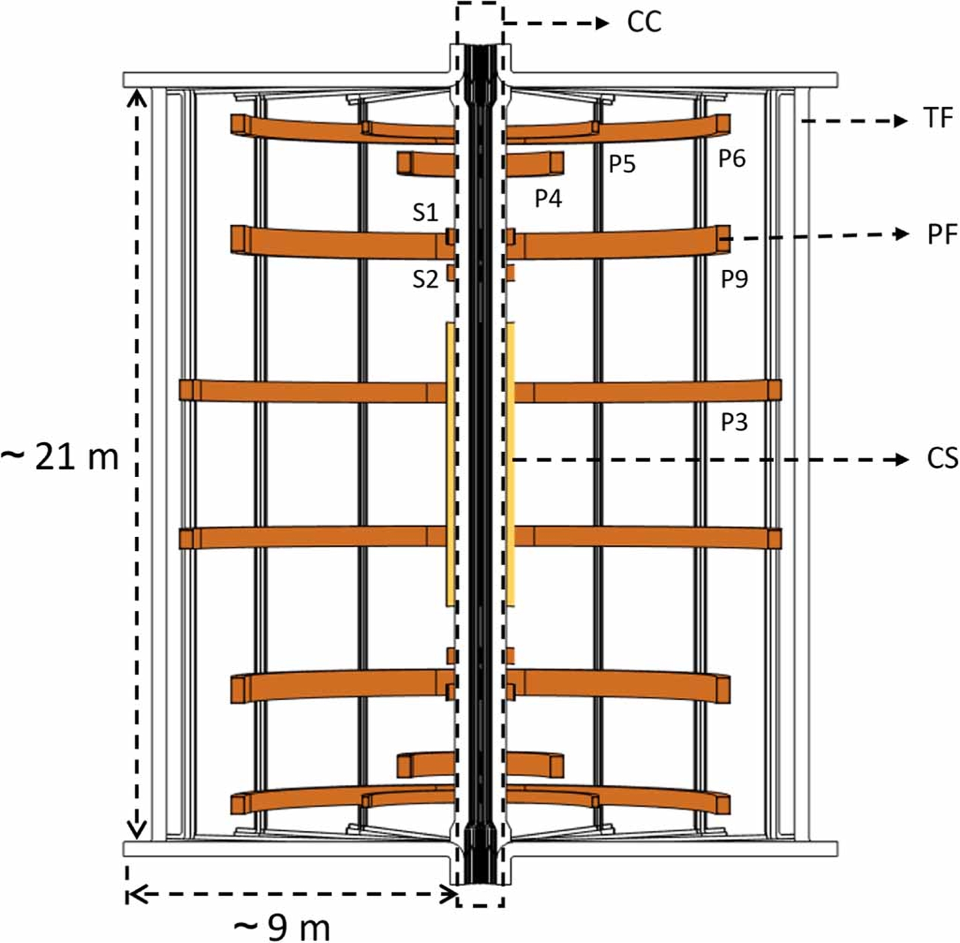
However, high-field operation imposes stringent requirements on magnet performance and thermal management. In particular, accurately quantifying AC losses in the HTS magnet system is a key design challenge. During plasma initiation, the charging and discharging of the central solenoid (CS) and poloidal field (PF) coils generate rapidly varying electromagnetic fields throughout the magnet system. These ramping processes give rise to AC losses within the CS and PF coils themselves. At the same time, the time-dependent magnetic fields produced by these coils induce screening currents in the toroidal field (TF) cables. Although the TF coils operate with direct current (DC), their exposure to transient background fields leads to additional AC losses that must be understood and controlled to preserve thermal margin and ensure reliable operation.
To address this challenge, STEP Fusion worked with Demcon Multiphysics to develop models of all the CS, PF, and TF coils and evaluate the resulting electromagnetic losses under representative operating scenarios.
STEP's Magnet System
STEP's magnet system (Figures 1 and 2) is designed to include 16 TF magnets, each containing 40 turns. Each of these turns consists of a vertically stacked tape (VST) cable that contains 230 individual HTS tapes. The coils work together to initiate and confine the plasma. The CS induces the plasma current, while the TF and PF coils collectively control the plasma’s position and shape.
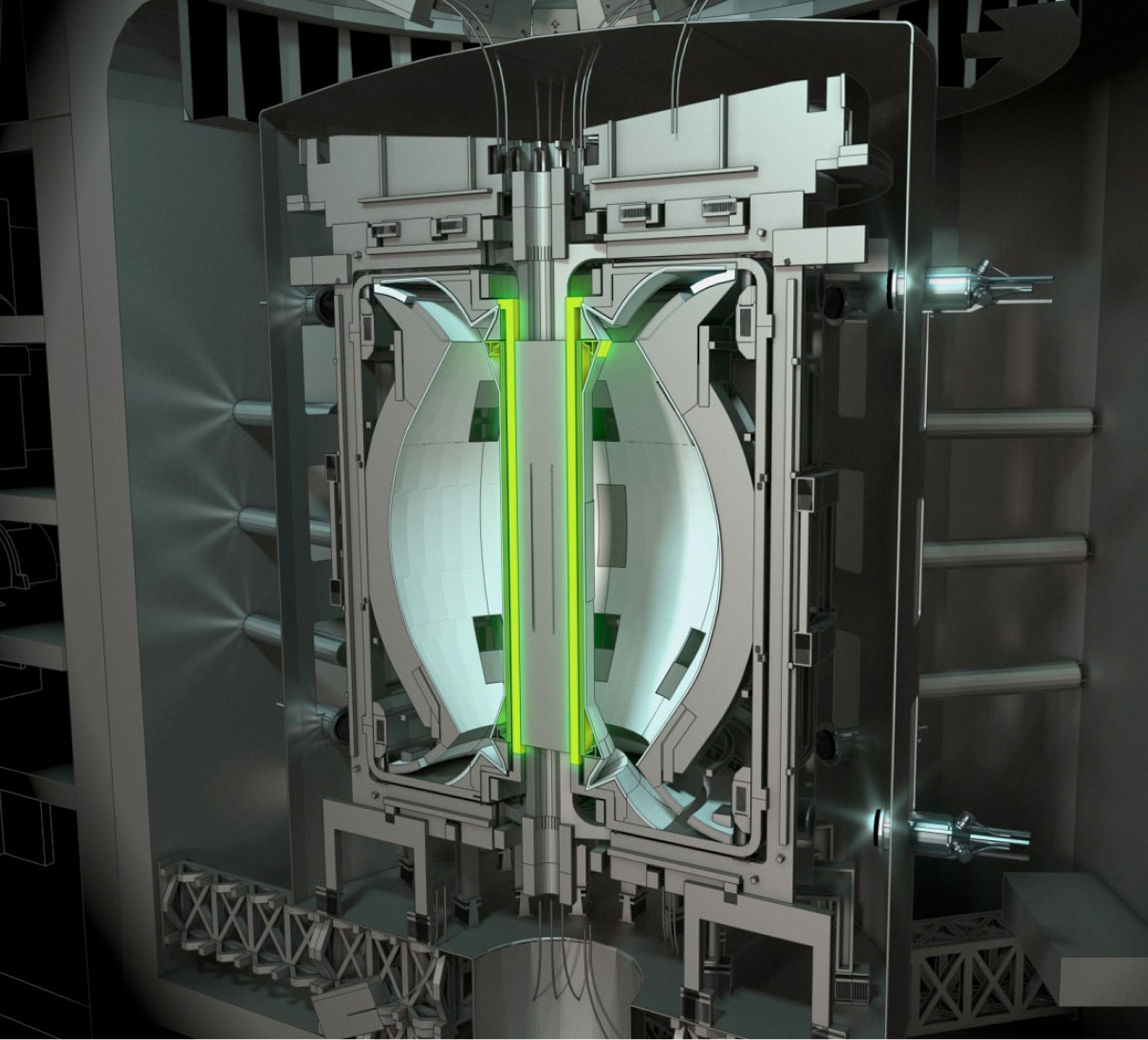
"With a high field, we can increase fusion power density and improve the efficiency of a spherical tokamak power plant, which can help reduce costs and support a more sustainable fusion energy system. That is a strategic target of the STEP program and why we chose to use the HTS magnets," said Jiabin Yang, a principal engineering analyst who works on the STEP program. “Importantly, the fusion power density in magnetic confinement systems increases strongly with magnetic field strength, following a high-order scaling with the field, and the recent development of HTS tapes capable of operating at such high fields has been a key enabler for advanced spherical tokamak concepts.”
AC Losses in Magnets
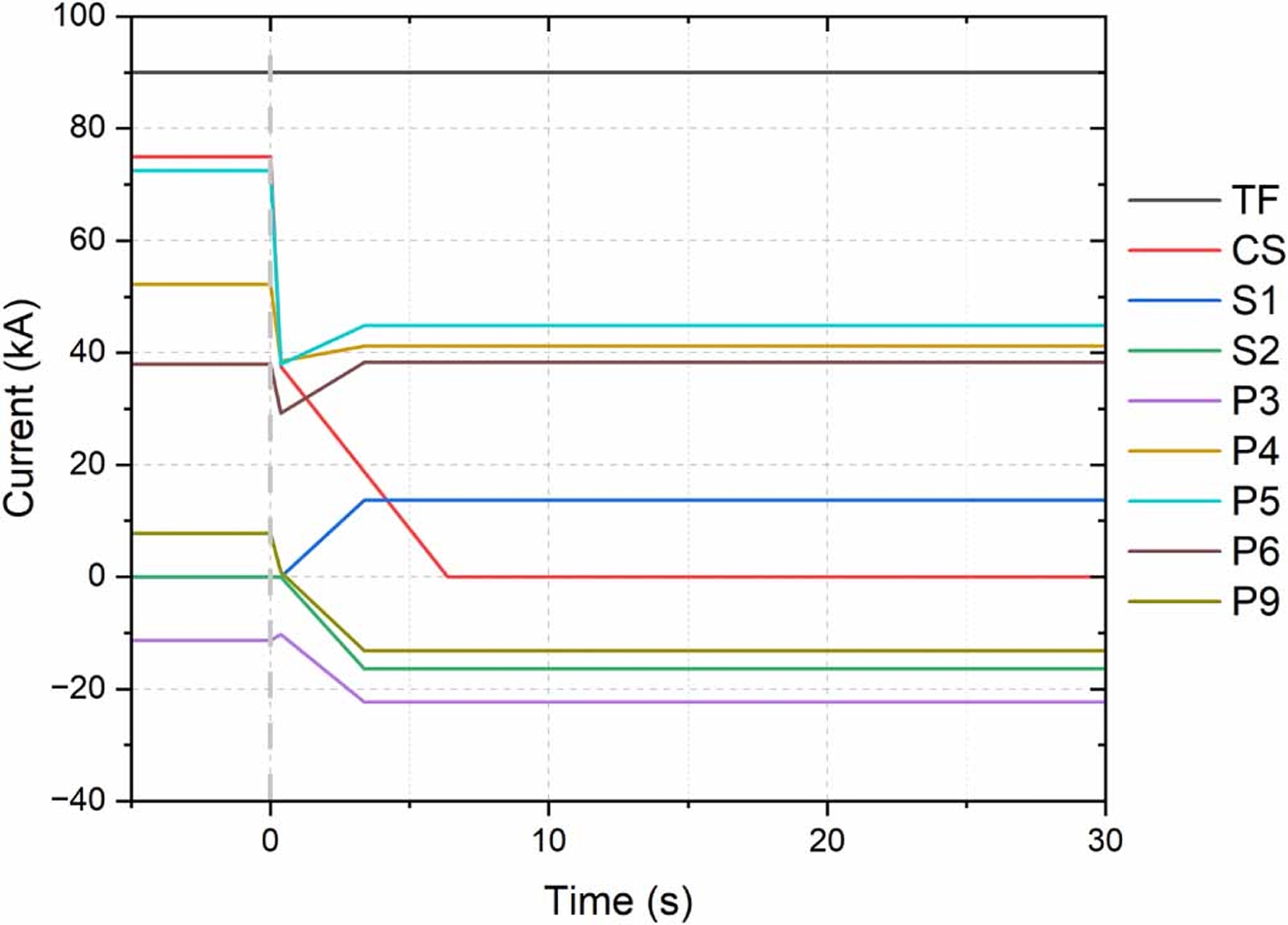
AC losses arise from time-varying electromagnetic fields that induce currents and magnetization, posing a significant hurdle because they create localized heating in magnets, shrink the thermal margin, and increase quench risk. The losses fall into three categories: hysteresis, coupling, and eddy current loss. Hysteresis losses arise in superconductors under time-varying electromagnetic conditions, such as changing magnetic fields or transport currents. Coupling losses result from currents induced between electrically connected superconducting and normal conducting elements. Eddy current losses occur in normal conducting components due to induced closed-loop currents, with all mechanisms ultimately dissipating energy as heat. AC losses arise during the plasma initiation phase, in which a quick discharge of the CS (within 0.37 s) provides the inductive drive for plasma current. The ramping of the CS and PF coils generates time-varying magnetic fields throughout the magnet system, giving rise to AC losses both within the CS and PF coils but also in the TF coils (despite their DC operation), mainly through screening currents within the HTS cable. In the center column, the inner limbs of the TF coils passing through the CS, where the magnetic flux density reaches its highest values (up to ~20 T), are therefore particularly affected. Using an assumed current profile (Figure 3), Yang, multiphysics engineer Rien Wesselink of Demcon, and their respective teams tested the distribution of hysteresis losses and eddy current losses in one of the TF limbs formed from HTS cables.
Simulation Methodology
When modeling the AC losses, STEP and Demcon used a multilevel simulation strategy tailored to different parts of the magnet system.
CS and PF Coil Modeling
The losses in the CS are determined through a 2D axisymmetric finite element model (Figure 4). Although the field from the TF coils is strictly not axisymmetric, a good estimation can be made by taking a conservative cross section of the TF field and imposing that as a background field. The magnetic field from the CS and PF is then imposed as a background field in a 2D planar infinitely long model used to simulate the AC losses generated in the inner TF limb.
TF Coil Modeling
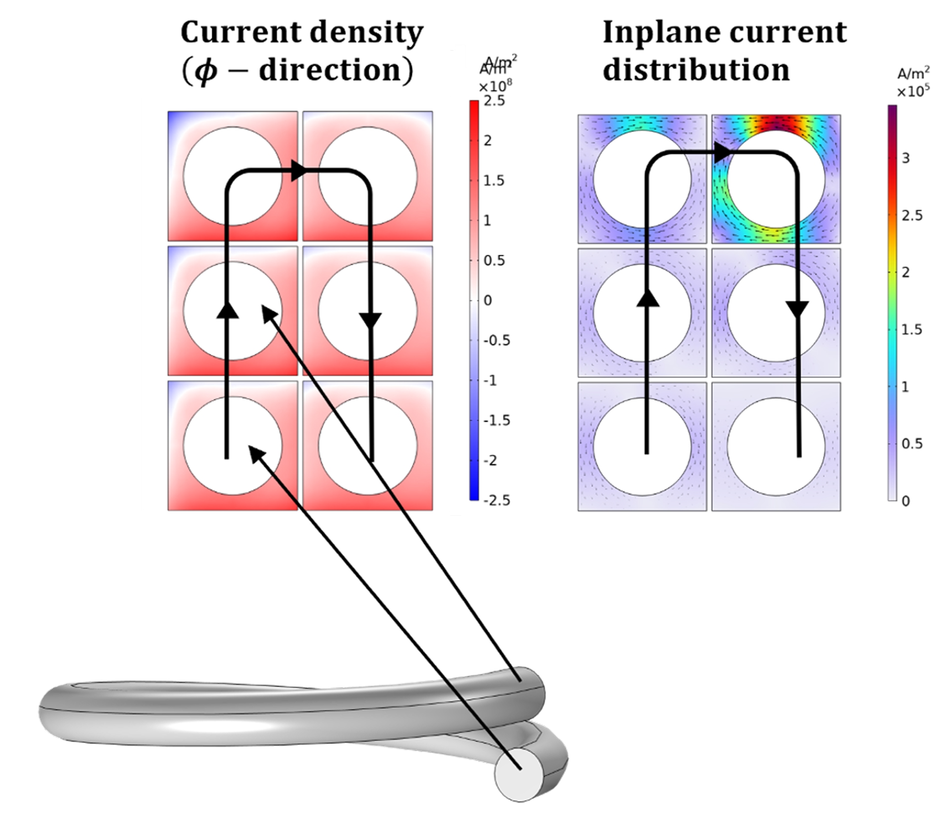
Demcon then modeled the AC losses in the TF conductors, including hysteresis and eddy current contributions, using a 2D planar model. For this modeling, the researchers needed a formulation method that was able to accurately quantify the different induced currents throughout the geometry. For this reason, Demcon used an H–H0–Φ formulation (a method that works around the need for a finite conductivity value in nonconducting domains) to model the magnetic properties of the superconducting materials. This approach splits the computational domain into conducting and nonconducting domains in order to optimize the simulation and to determine the energy losses along the TF magnet center column limb.
"We used the H–H0–Φ formulation, which we implemented into COMSOL Multiphysics®," Wesselink said. "There are two interfaces, the Magnetic Field Formulation (MFH) interface and the Magnetic Fields, No Currents interface, that we coupled together. The advantage of this approach is that, compared to just the H formulation, you can have domains with zero conductivity."
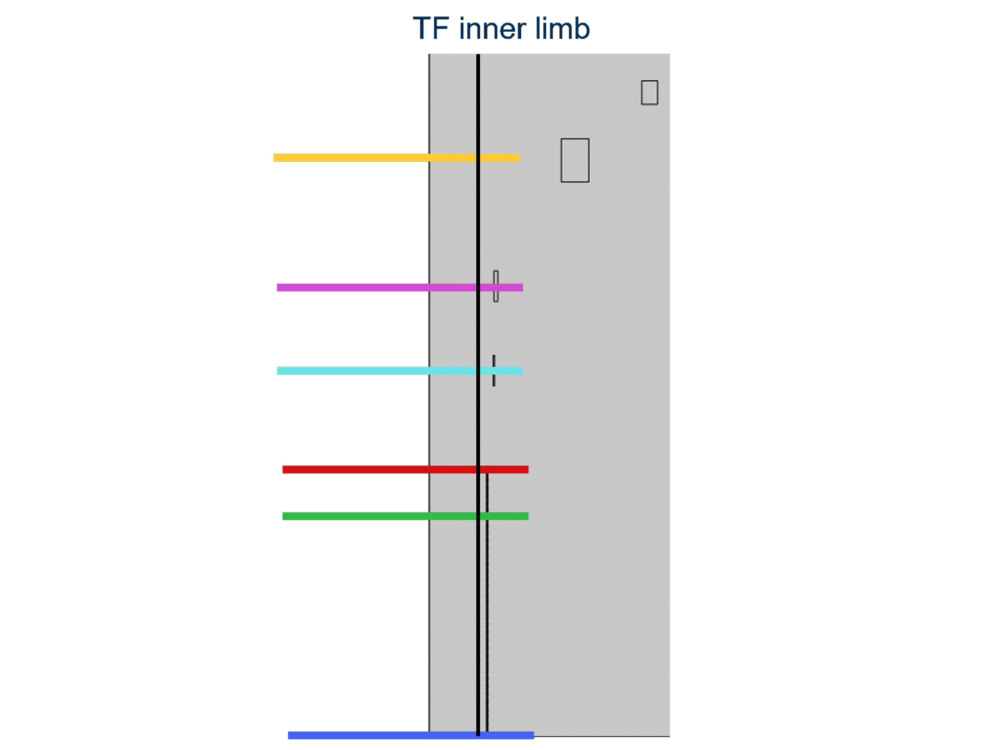
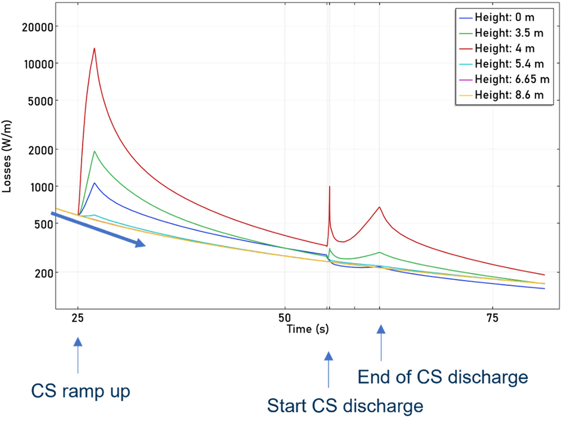
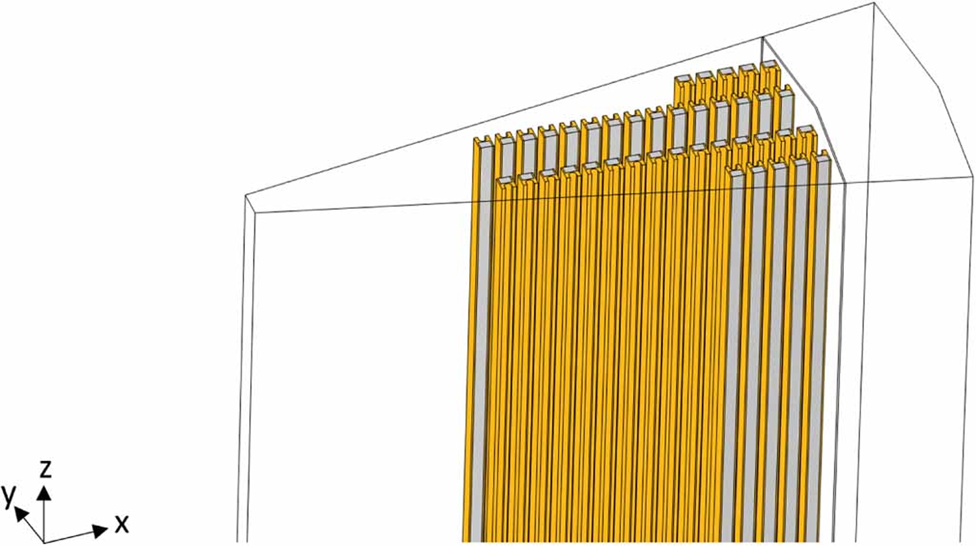
While one could use 3D simulations to investigate the losses in the TF limbs in the center column, Yang, Wesselink, and their respective teams found these simulations to be quite time-consuming to set up, mesh, and run. Instead, a computationally efficient 2D cross-sectional approach was adopted. Multiple cross sections were evaluated along the length of the TF inner limb, and the total losses were obtained by integrating the results, thereby capturing the longitudinal variation without requiring a full 3D model.
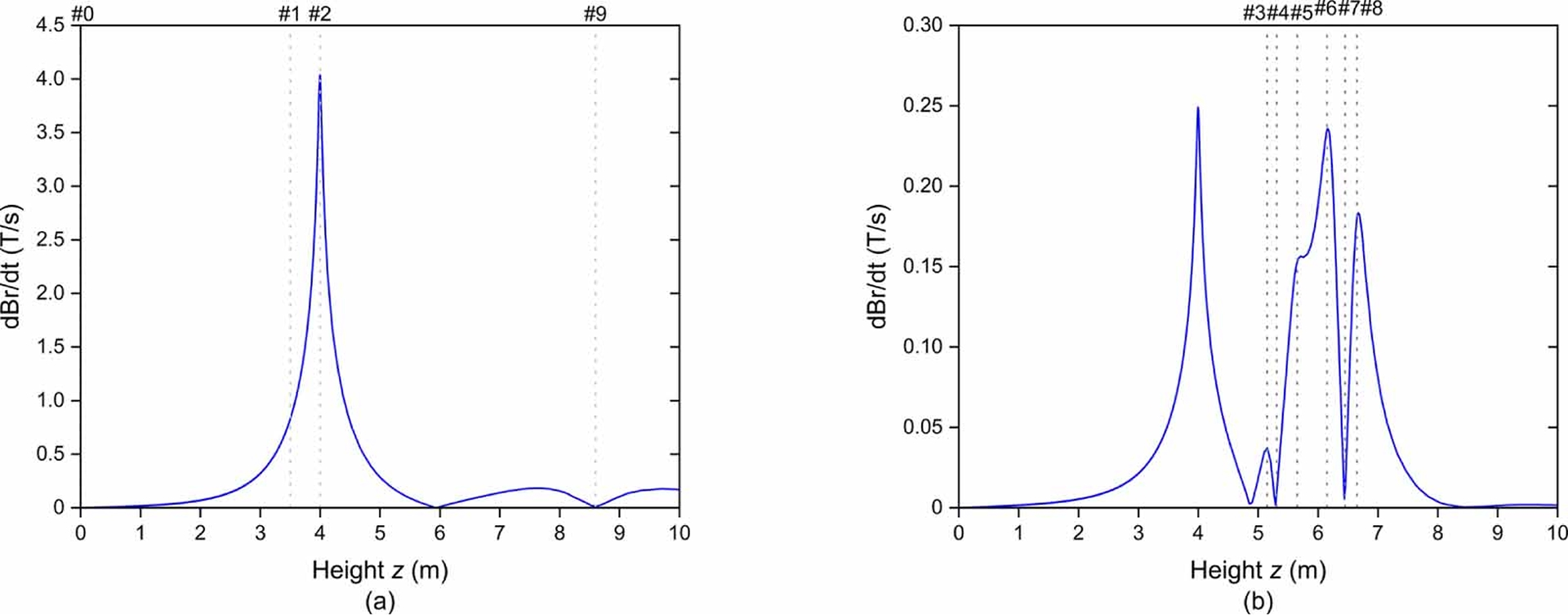
"We assumed that the fields and currents varied slowly in the z direction (along the central axis of the tokamak), so we can take multiple 2D (xy) cross sections at different z-locations," Wesselink said. "Then we added the background fields from the CS and PF coils that were extracted from a simplified 2D axisymmetric calculation." The time derivative of the abovementioned fields is shown in Figure 6.
Estimating the Coupling Losses in TF
In STEP's TF cables, ReBCO tapes are stacked together, and this is an area that may exhibit nonnegligible coupling losses. The teams used a 3D resistive coupling model to calculate these losses. Figure 7 shows the different B-field components of the CS and the corresponding coupling currents they would induce in the TF coil conductors. Analytic estimations of these currents result in the conclusion that these are negligible contributions in the overall AC losses picture.
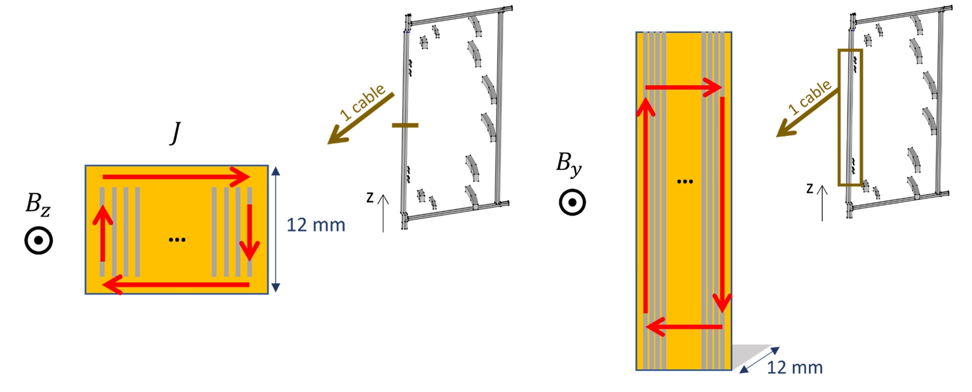
Yang's and Wesselink's teams verified the analytical estimations mentioned above with 3D calculations that approximated the tape stack as a perfect conductor in the directions parallel to the tape and a normal conductor in the direction perpendicular to the tape. They found that the estimates were largely correct but that the eddy currents in the copper support are relevant.
Looking into the Thermal Effects of AC Losses in TF
All of this modeling and simulation pointed to the hysteresis losses in the ReBCO tapes being the dominant source of AC loss in STEP. These losses are localized around the ends of the CS magnet and the S1 PF magnet near the center column, and they scale with the magnetic field ramp rate. These losses, as predicted, will result in temperature increases.
"It costs an enormous amount of power to cool these fusion systems," Wesselink said. "All these losses require more input power for the cryogenic cooler."
Thus far, STEP and Demcon have completed a preliminary estimation on the temperature rise that can be expected within the TF. The temperature distribution, based on the calculated hysteresis, eddy current, and coupling losses at representative positions, can be seen in Figure 9.
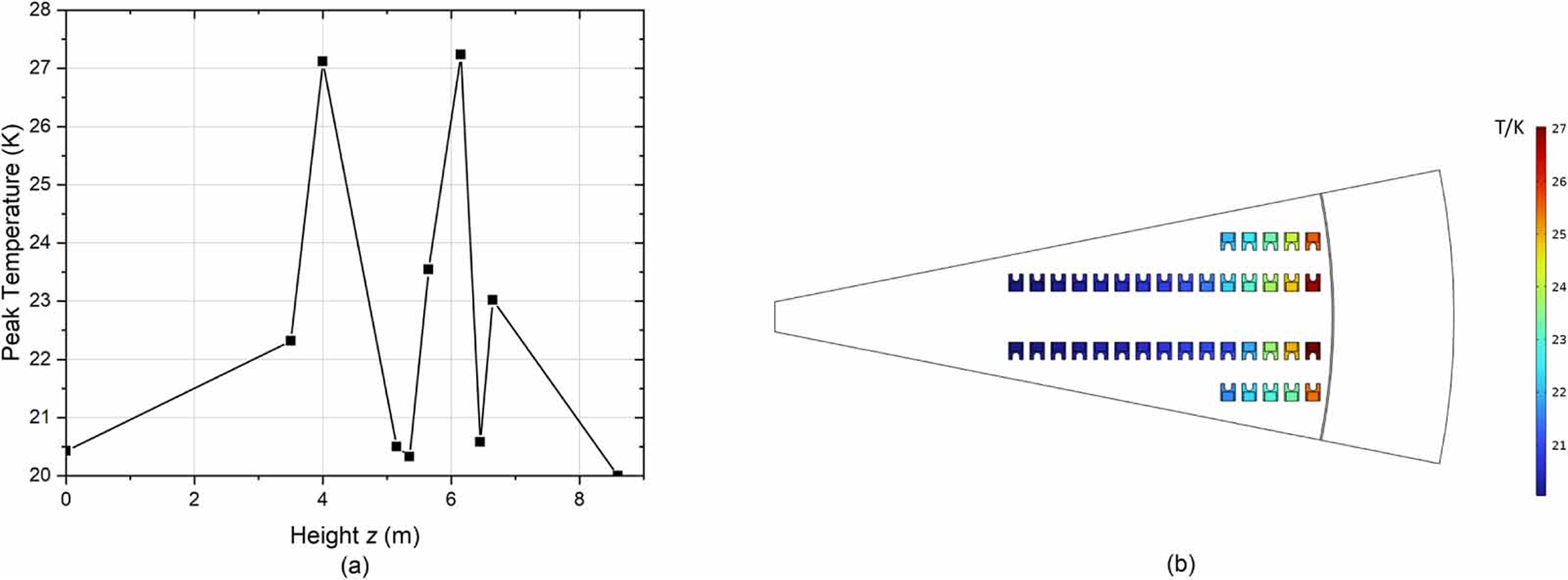
The teams found that the temperature rise associated with the AC losses in TF is sufficiently low and that additional mitigation such as twisting or transposition is not required. For these reasons, they could use a simpler TF cable design that improves the manufacturability and efficiency of the HTS cables while keeping temperature rise within acceptable limits.
Moving Forward with STEP
The STEP program is well underway as its designers and engineers take on the numerous challenges associated with fusion power. In support of this effort, UK Fusion Energy Ltd. is continuing to work with Demcon Multiphysics to gain insight into the complex systems and phenomena and adjust the tokamak design accordingly.
The teams are currently working on 3D quench simulations of STEP's TF coils. These simulations are designed to evaluate potential quench protection strategies. To keep these calculations tractable, the respective teams have developed a new method (also implemented in COMSOL®) to approximate all the cables as lines. Thus far, simulation has been an integral part of that journey, and according to Yang and Wesselink, it will continue to be in the future.
Reference
- J. Yang et al., "AC losses in the STEP TF magnet during plasma initiation," Superconductor Science and Technology, vol. 38, issue 5, 2025.
Acknowledgement
This work has been funded by STEP Fusion, a major technology and infrastructure program led by UK Fusion Energy Ltd., which aims to deliver the UK’s prototype fusion power plant and a path to the commercial viability of fusion.
Suggested Stories
Defending Automotive Components Against Corrosive Destruction
Galvanic corrosion, which occurs when the surfaces of different adjoining metals begin to degrade, costs the ...
Keynote: Simulation of MEMS Sensors at Bosch
In this keynote talk at the COMSOL Conference 2025 Amsterdam, Daniel Maier of Bosch discusses MEMS sensors and the ...
On the Cutting Edge of Hearing Aid Research
Nearly 20% of the United States population has some degree of hearing impairment. Despite the relative ...
Greening the Heart of the City: An Urban Rooftop Drainage System Inside a Garden Fence
TL-Engineering, a simulation consultant, teamed up with a professor, civil engineer, and sound barrier company to ...


