Aggiornamenti Rotordynamics Module
Per gli utenti del Rotordynamics Module, la versione 6.4 di COMSOL Multiphysics® introduce una nuova funzionalità che consente di definire facilmente le proprietà rotazionali, funzionalità ampliate per i coefficienti dinamici e una nuova opzione per tracciare le modalità proprie come funzioni di un parametro. Proseguite la lettura per ulteriori dettagli su questi aggiornamenti.
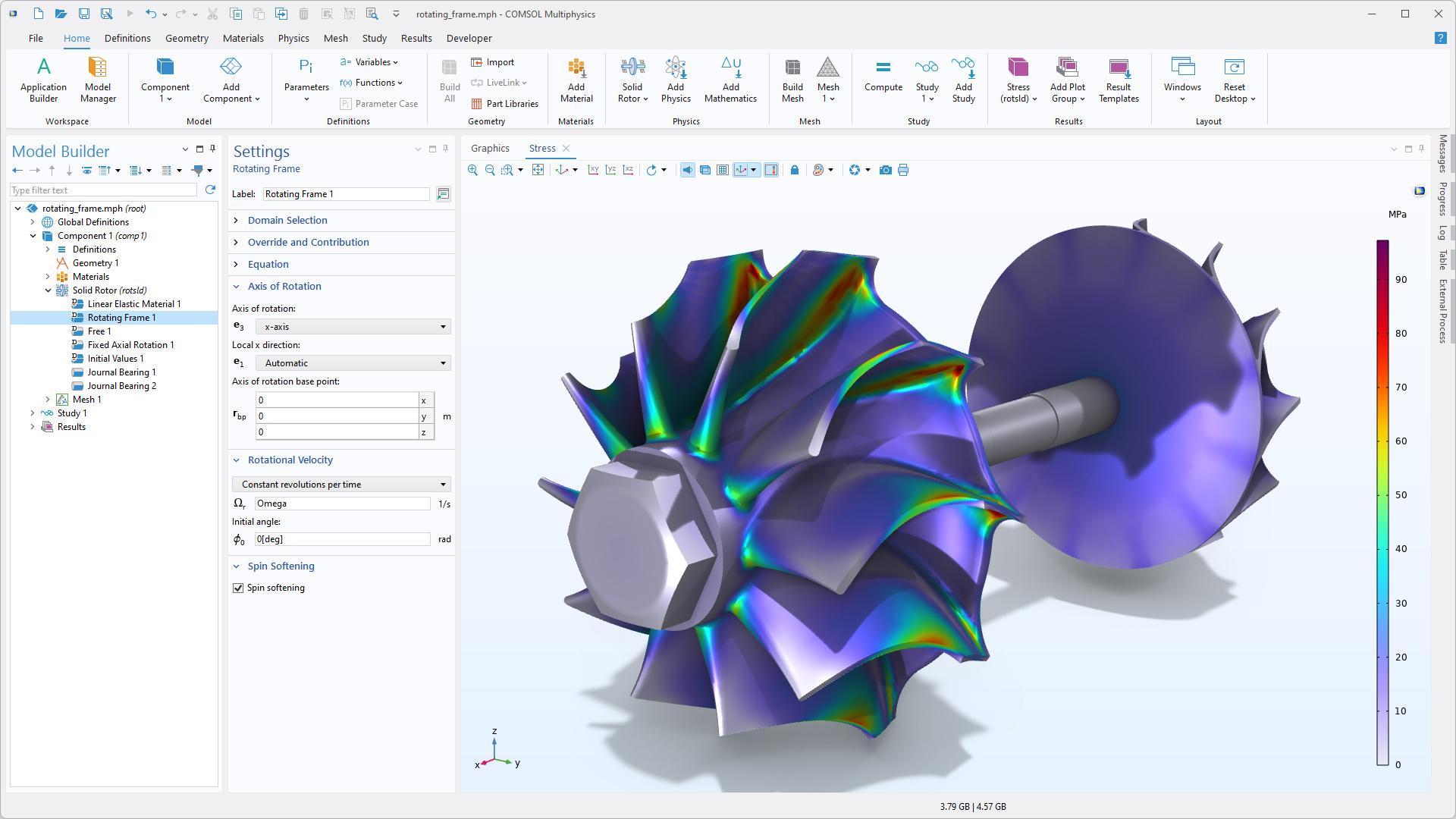
Rotating Frame nelle interfacce Solid Rotor
Quando si modellano sistemi con più rotori, come turbine, motori o alberi a gomiti, l'impostazione e il controllo dei parametri di rotazione sono ora più semplici ed efficienti. Una nuova funzione predefinita, Rotating Frame, è stata introdotta nelle interfacce Solid Rotor e Solid Rotor, Fixed Frame. Oltre a migliorare le prestazioni, questa funzione consolida tutte le impostazioni relative alle proprietà di rotazione e offre un maggiore controllo sulle quantità definite, come l'asse di rotazione e la velocità angolare. È possibile vedere questo miglioramento nei tutorial Comparison of Campbell Diagrams Using Different Rotor Interfaces e Rotordynamic Analysis of a Crankshaft.
Funzionalità estesa per la determinazione dei coefficienti dinamici
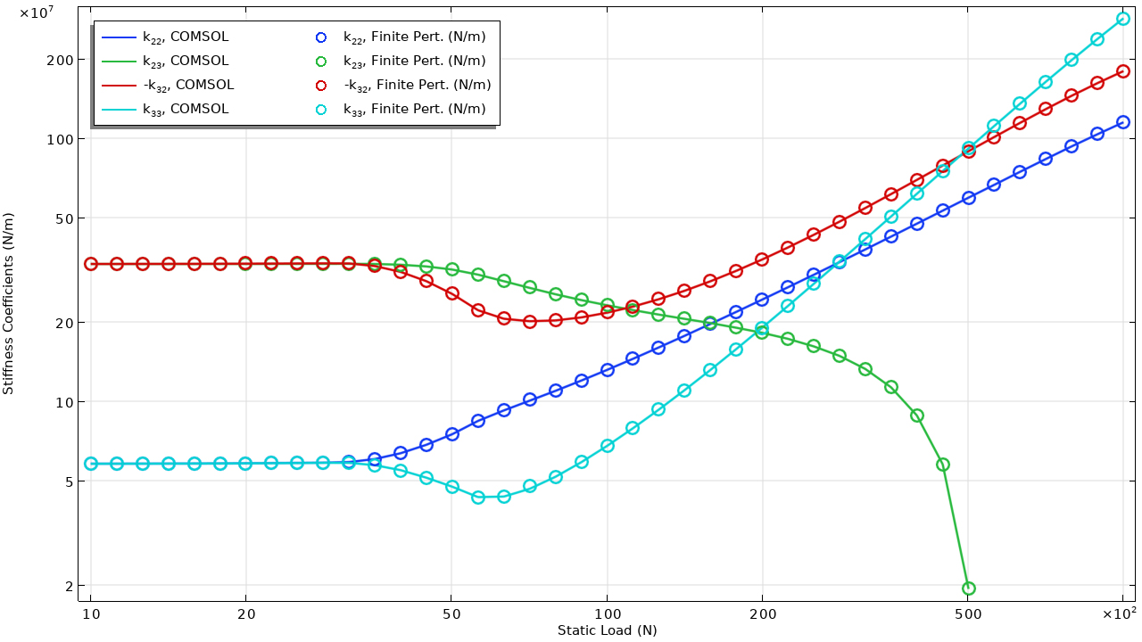
Per un'analisi più accurata delle prestazioni dei cuscinetti e delle interazioni rotore-cuscinetto, i calcoli dei coefficienti dinamici sono ora più robusti e versatili. L'interfaccia Hydrodynamic Bearing è stata migliorata per consentire il calcolo accurato dei coefficienti di rigidità e smorzamento linearizzati in qualsiasi condizione al contorno disponibile.
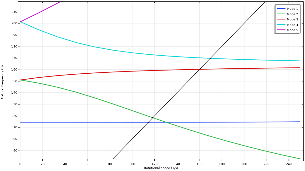
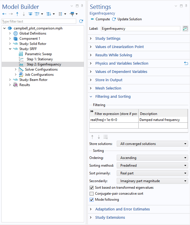
Mode Following per lo studio delle frequenze proprie
Per facilitare l'interpretazione e l'identificazione delle potenziali velocità critiche nei diagrammi di Campbell, ora è possibile tracciare continuamente le modalità proprie durante l'analisi. Questa funzionalità è resa possibile dalla nuova opzione Mode following disponibile per i tipi di studio delle frequenze proprie. I seguenti tutorial dimostrano questa funzionalità aggiuntiva:
Nuovo tutorial
La versione 6.4 di COMSOL Multiphysics® introduce un nuovo tutorial nel Rotordynamics Module.
Validation of Dynamic Coefficients in Hydrodynamic Bearings
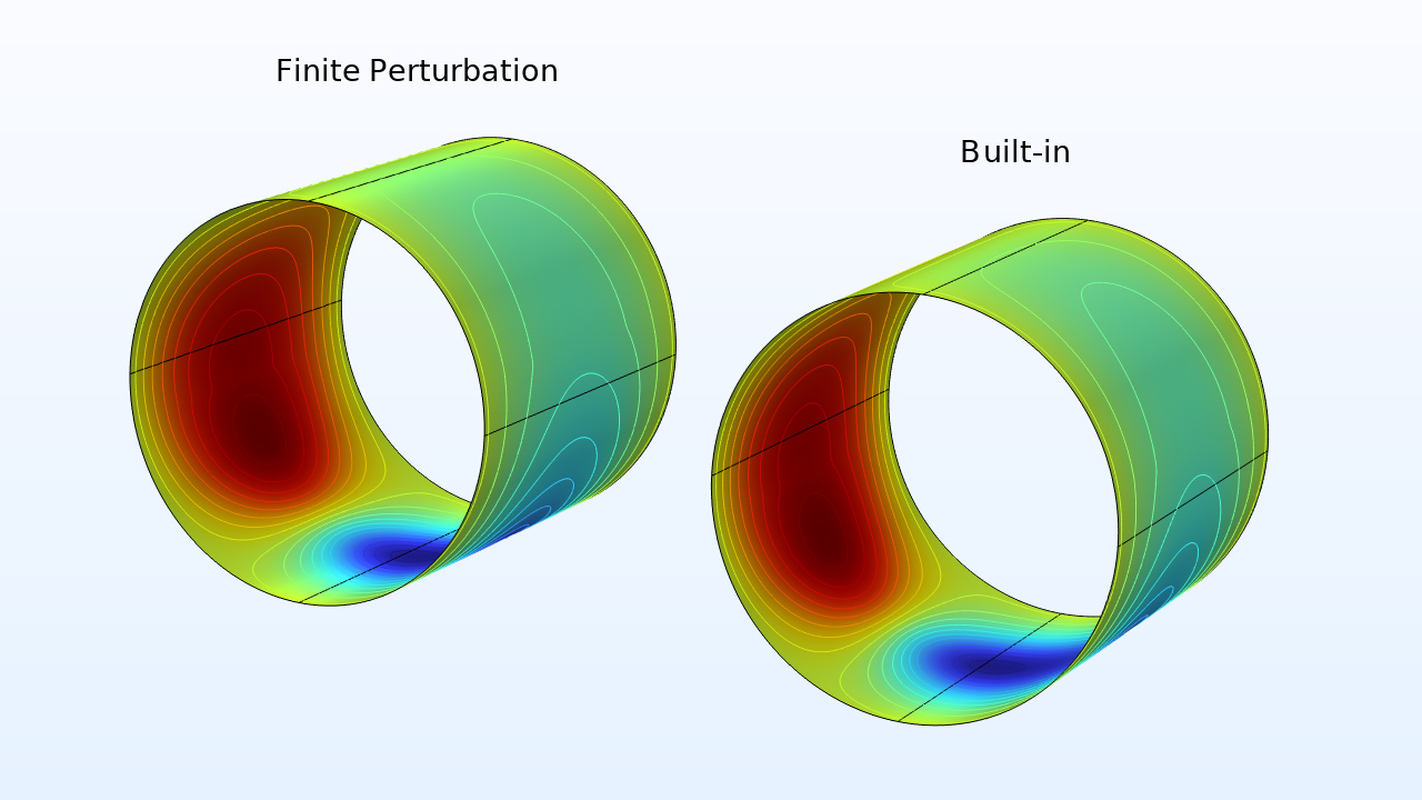
dynamic_coefficients_finite_perturbation
Download da Application Gallery