Aggiornamenti RF Module
Per gli utenti dell'RF Module, la versione 6.4 di COMSOL Multiphysics® introduce una modellazione semplificata delle linee di trasmissione, una nuova funzionalità per la progettazione ottimizzata dei metamateriali e funzionalità avanzate per l'analisi del campo lontano per l'ottimizzazione e l'analisi della polarizzazione. Proseguite la lettura per ulteriori dettagli su questi aggiornamenti.
Modellazione migliorata delle linee di trasmissione
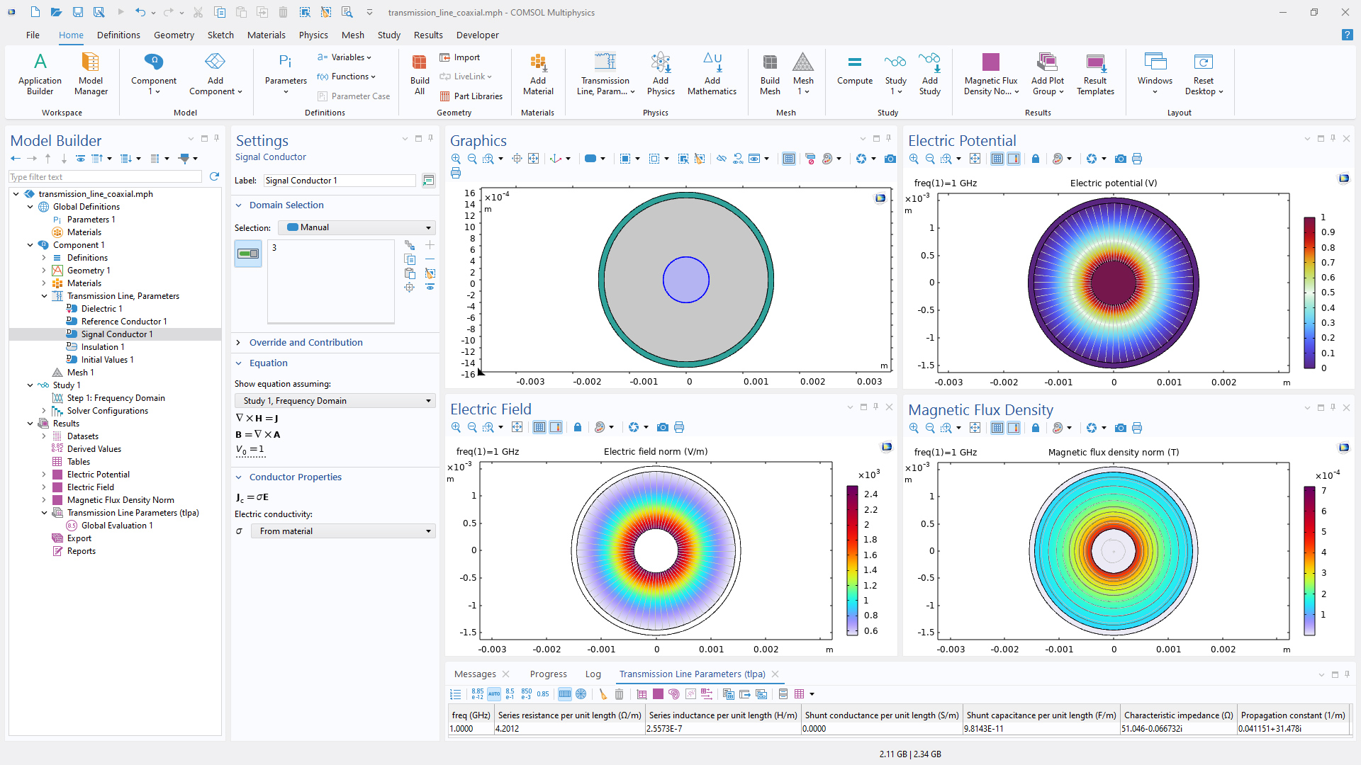
La nuova interfaccia Transmission Line, Parameters sostituisce una complessa configurazione multifisica con configurazioni semplificate. Calcola la resistenza in serie, l'induttanza in serie, la conduttanza in shunt e la capacità in shunt per unità di lunghezza, nonché l'impedenza caratteristica e la costante di propagazione per linee di trasmissione a due conduttori. Il calcolo viene eseguito nel dominio della frequenza utilizzando la modellazione 2D ed è illustrato nel tutorial Transmission Line Parameters of a Coaxial Cable.
Le configurazioni multiconduttori sono ora supportate nell'interfaccia Transmission Line attraverso più variabili dipendenti. I parametri degli elementi distribuiti sono definiti come matrici quadrate dimensionate in base al numero di conduttori. Inoltre, sono ora supportate le caratteristiche degli elementi in serie e in shunt, che offrono una maggiore flessibilità di modellazione.
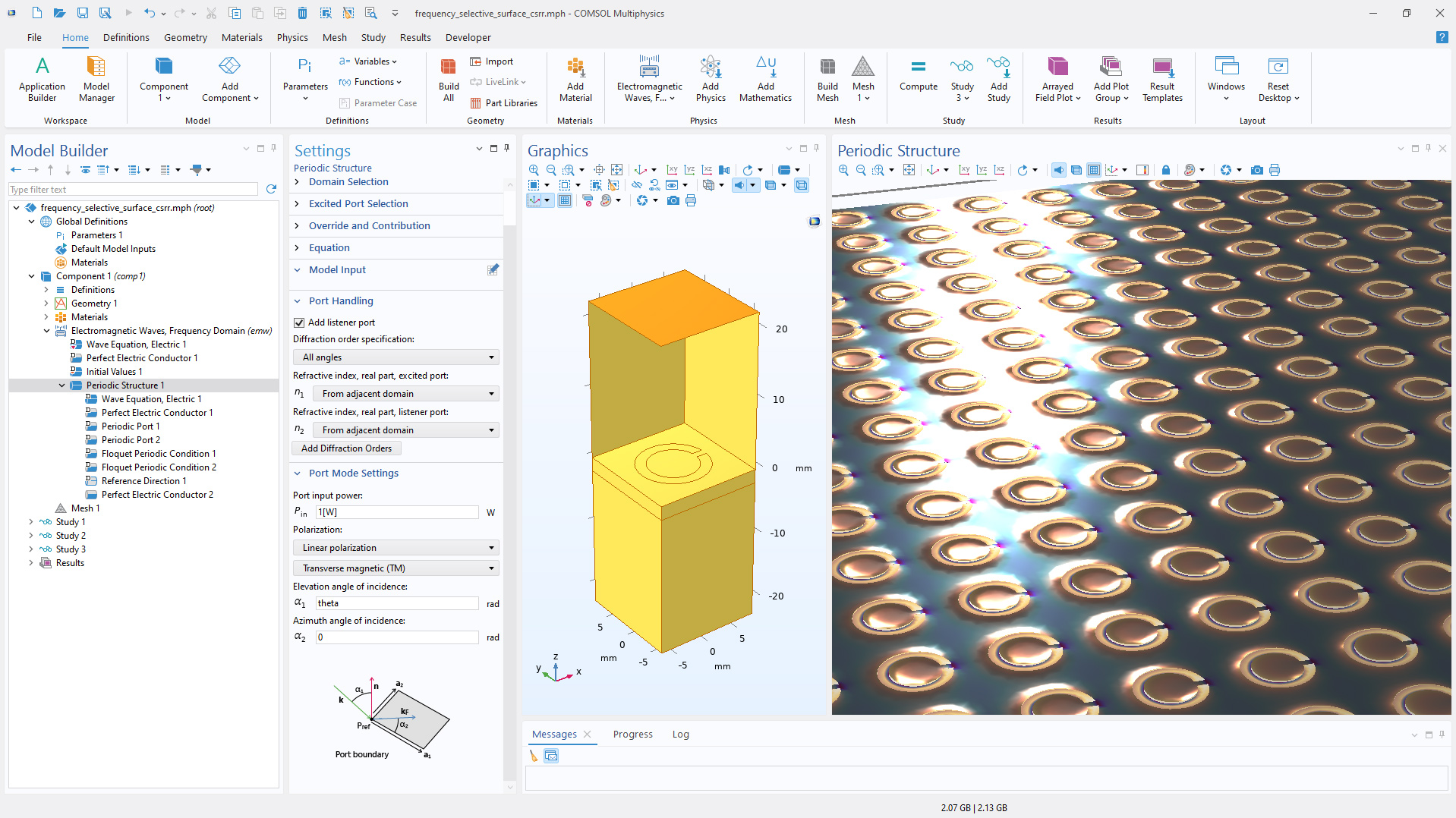
Struttura periodica per la modellazione semplificata dei metamateriali
Per semplificare la modellazione delle strutture periodiche e dei metamateriali, la nuova funzione Periodic Structure, disponibile nell'interfaccia Electromagnetic Waves, Frequency Domain, offre le funzioni predefinite Periodic Port e Floquet Periodic Condition. I tutorial Fresnel Equations (RF) e Frequency Selective Surface, Periodic Complementary Split Ring Resonator mostrano questo aggiornamento.
Funzionalità avanzata per il campo lontano
Le funzioni per il campo lontano sono ora disponibili per l'ottimizzazione, consentendo studi di ottimizzazione della forma che migliorano il guadagno dell'antenna. Il nuovo tutorial Optimizing the Front End of a Conical Horn Lens Antenna dimostra questa possibilità. Inoltre, sono state introdotte nuove variabili, EfarLHCP e EfarRHCP, per calcolare le componenti di polarizzazione circolare sinistrorsa e destrorsa nelle analisi del campo lontano.
La radiazione del campo lontano in presenza di un substrato può anche essere analizzata utilizzando la nuova funzione Far-Field Domain, Inhomogeneous. Questa nuova funzione supporta il calcolo del campo lontano per strutture costituite da un superstrato (aria) e un substrato dielettrico omogeneo, come mostrato nel tutorial Embedded Scatterer on a Substrate.
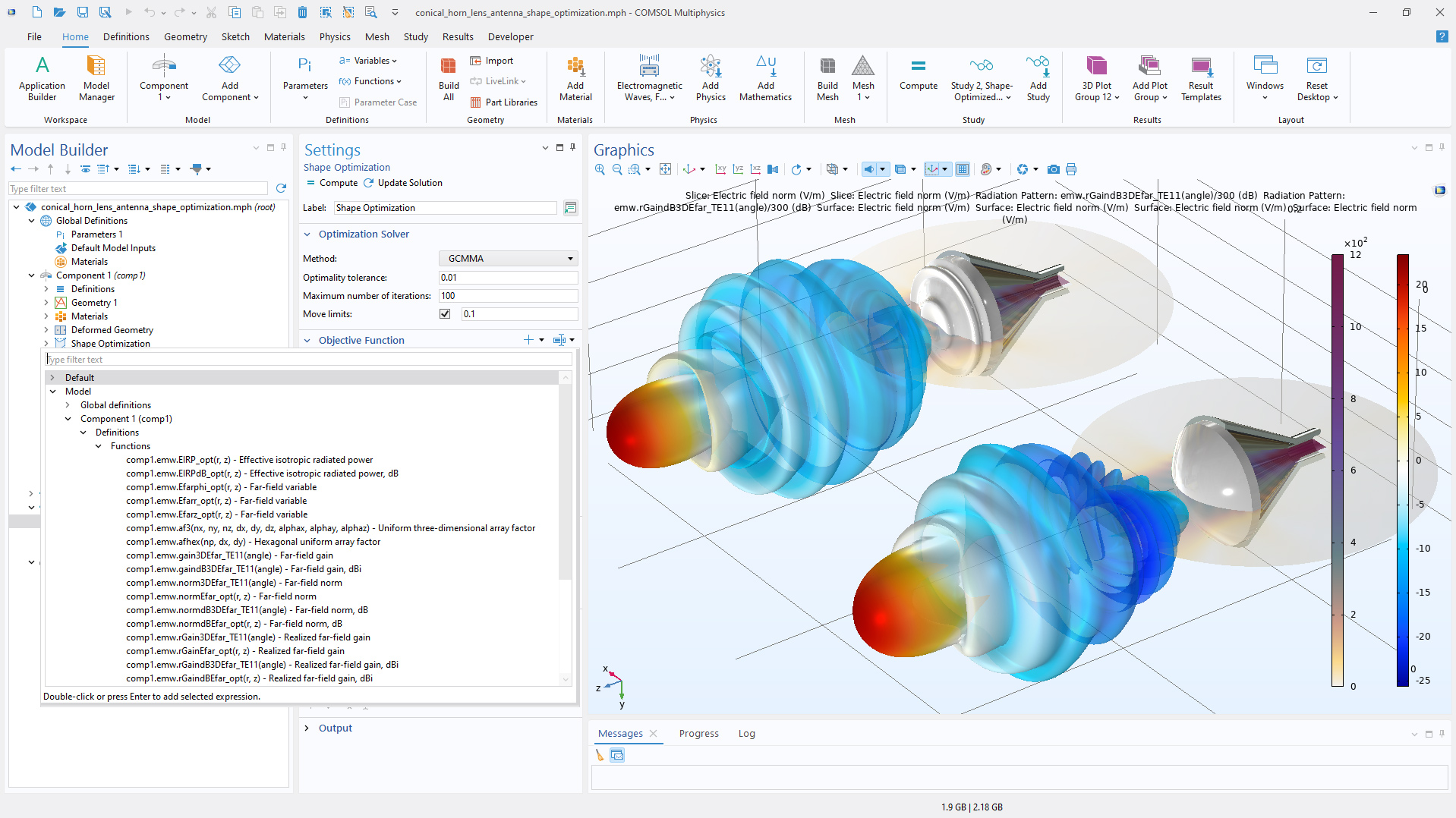
L'animazione mostra come il processo di ottimizzazione modifichi la geometria originale della lente per ottenere una versione con guadagno migliorato.
Nuove variabili per il calcolo dell'accoppiamento tra diversi contorni di origine e destinazione
Per semplificare l'analisi, ad esempio, dell'accoppiamento tra onde guidate e onde in spazio libero (e viceversa), sono state definite nuove variabili per l'efficienza di accoppiamento (ovvero il rapporto tra la potenza di uscita integrata e la potenza di ingresso). Le variabili sono accumulate gerarchicamente, facilitando l'analisi dell'accoppiamento sia con caratteristiche e contorni piccoli che grandi. Allo stesso modo, esiste una gerarchia di variabili per tenere conto della perdita integrata dovuta all'assorbimento. Sono disponibili variabili sia per la perdita di potenza che per la perdita normalizzata alla potenza in ingresso. Questa funzionalità è dimostrata principalmente nel modello Modeling a Scatterer Near an Optical Waveguide, ma può essere vista anche nei seguenti tutorial:
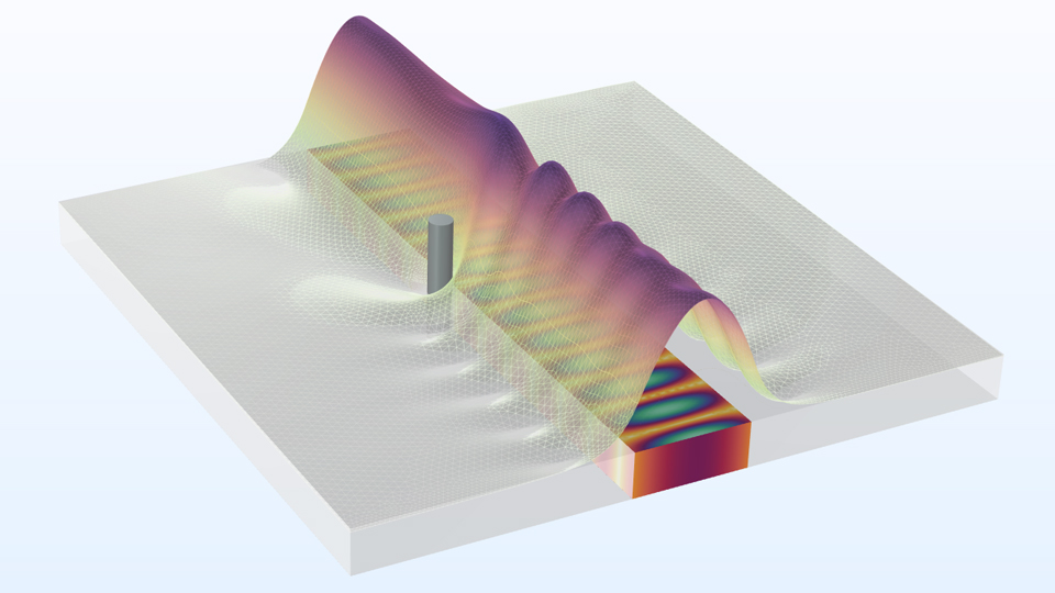
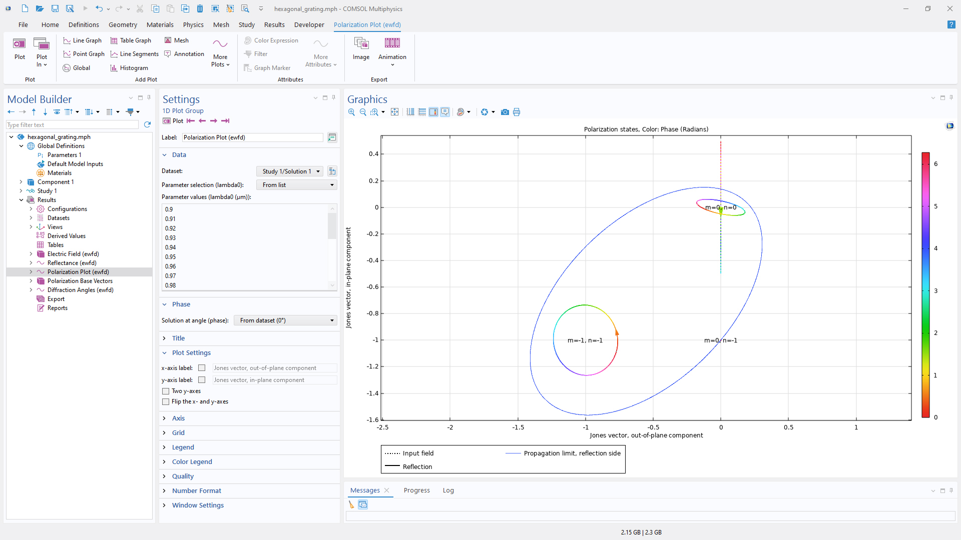
Grafico di polarizzazione aggiornato e miglioramenti dei risultati
Nel grafico Polarization è disponibile una nuova opzione per normalizzare le ellissi di polarizzazione alla massima efficienza di diffrazione. Di conseguenza, la dimensione dell'ellisse rappresenta l'efficienza di diffrazione. Inoltre, sono disponibili nuove opzioni di grafico che indicano l'area di propagazione degli ordini di diffrazione. Il grafico Polarization aggiornato è mostrato nei tutorial Hexagonal Grating (Wave Optics) e Hexagonal Plasmonic Color Filter.
La funzione Cross Section Calculation offre ora diverse opzioni per la modellazione delle sezioni trasversali di scattering, assorbimento ed estensione: un grafico predefinito o una valutazione globale, illustrati rispettivamente nei tutorial Optical Scattering off a Gold Nanosphere e Scatterer on Substrate.
I nodi Global Evaluation, come riflettanza, trasmittanza ed efficienza di diffrazione, sono stati raggruppati nei nodi Evaluation Group, consentendo l'aggiornamento automatico dei dati della tabella dopo simulazioni ripetute. Questa funzionalità è illustrata nel tutorial Waveguide S-Bend, in cui vengono valutati riflettanza, trasmittanza e perdita.
Nuovi tutorial
La versione 6.4 di COMSOL Multiphysics® introduce diversi nuovi tutorial nell'RF Module.
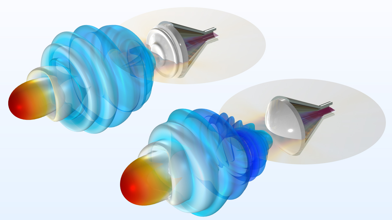
Optimizing the Front End of a Conical Horn Lens Antenna
conical_horn_lens_antenna_shape_optimization
Download da Application Gallery
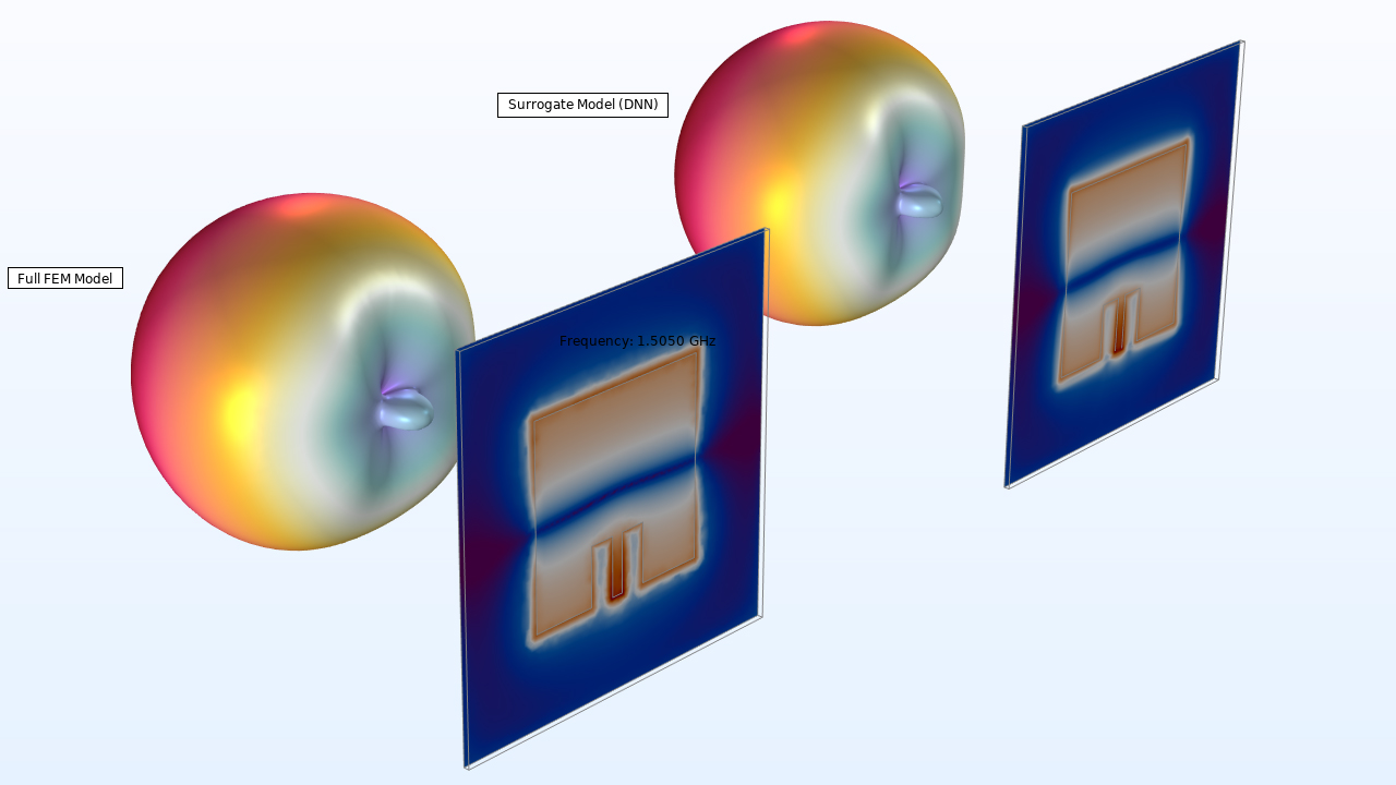
Microstrip Patch Antenna Surrogate Model
Embedded Scatterer on a Substrate
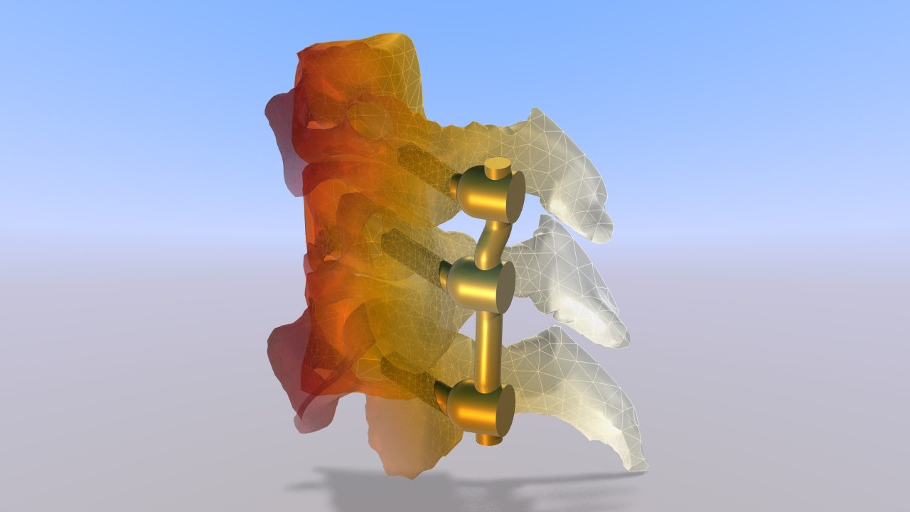
MRI Implant Heating
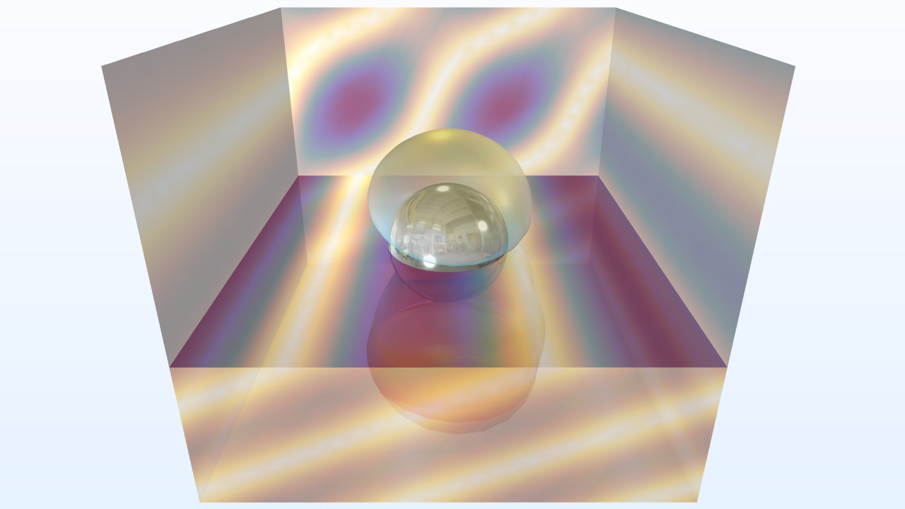
Efficient Modeling of a Spherical Radome