Aggiornamenti Composite Materials Module
Per gli utenti del Composite Materials Module, la versione 6.4 di COMSOL Multiphysics® introduce miglioramenti nella modellazione di shell stratificate e strutture stratificate, oltre a un nuovo tutorial. Proseguite la lettura per ulteriori dettagli su questi aggiornamenti.
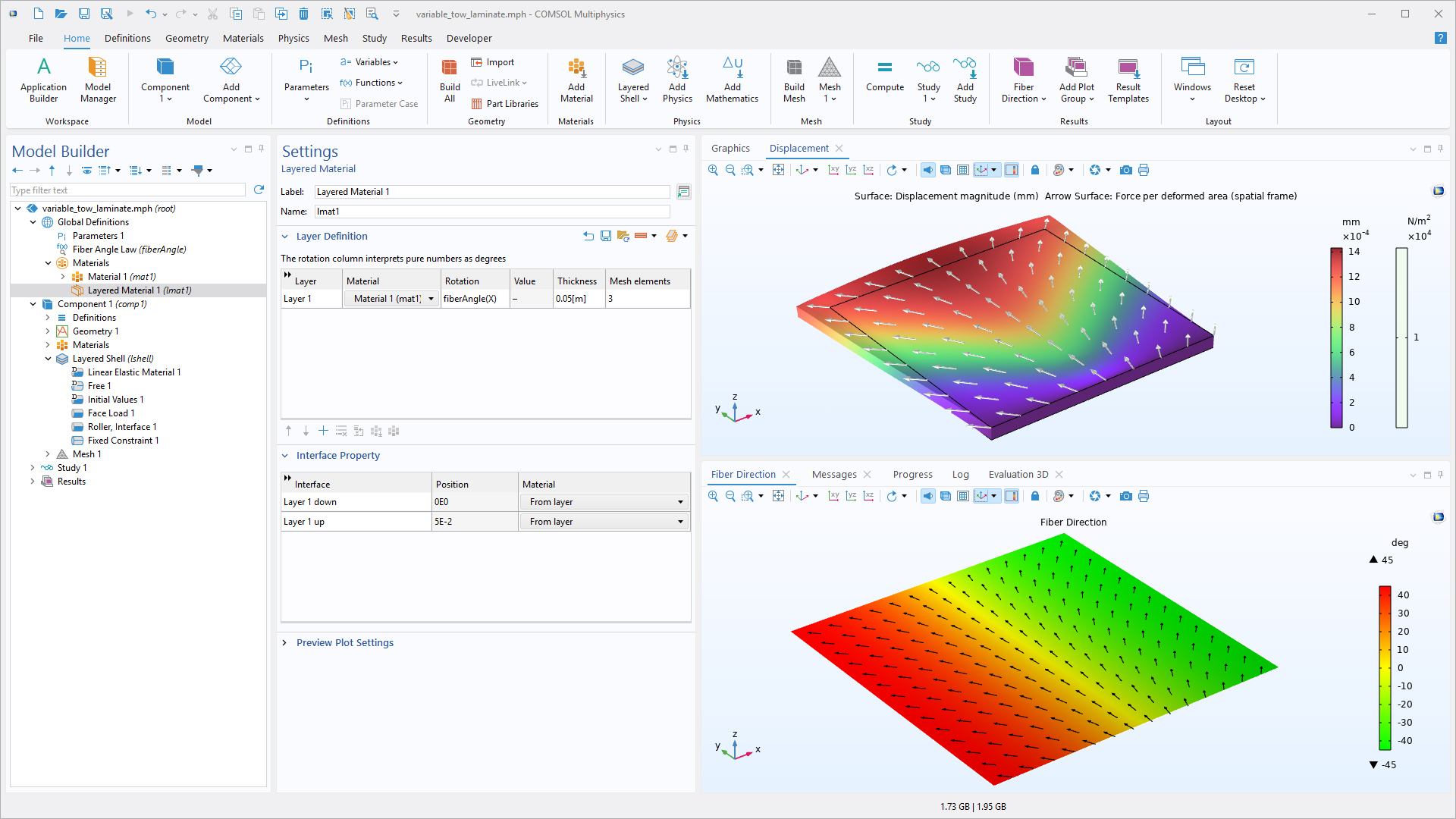
Miglioramenti all'interfaccia Layered Shell
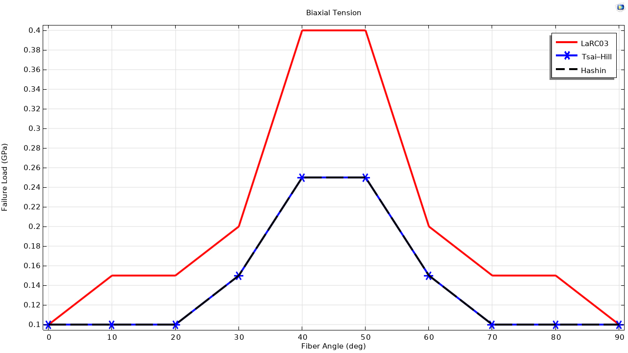
Nella versione 6.4, l'interfaccia Layered Shell include tre miglioramenti principali. L'angolo di rotazione immesso nel nodo Layered Material sotto Global Definitions può ora essere definito come variabile, consentendo la modellazione di laminati tow ad angolo variabile. Il grafico predefinito è stato aggiornato per visualizzare la componente del tensore di sollecitazione nella direzione della fibra e due template di risultati mostrano ora le componenti del tensore di sollecitazione della lamina o del laminato invece della sollecitazione di von Mises. Inoltre, sono state migliorate le formulazioni per i criteri di rottura LaRC03 e Hashin. È possibile visualizzare questi miglioramenti nel tutorial Parametric Study on Cross-Ply Laminate Failure.
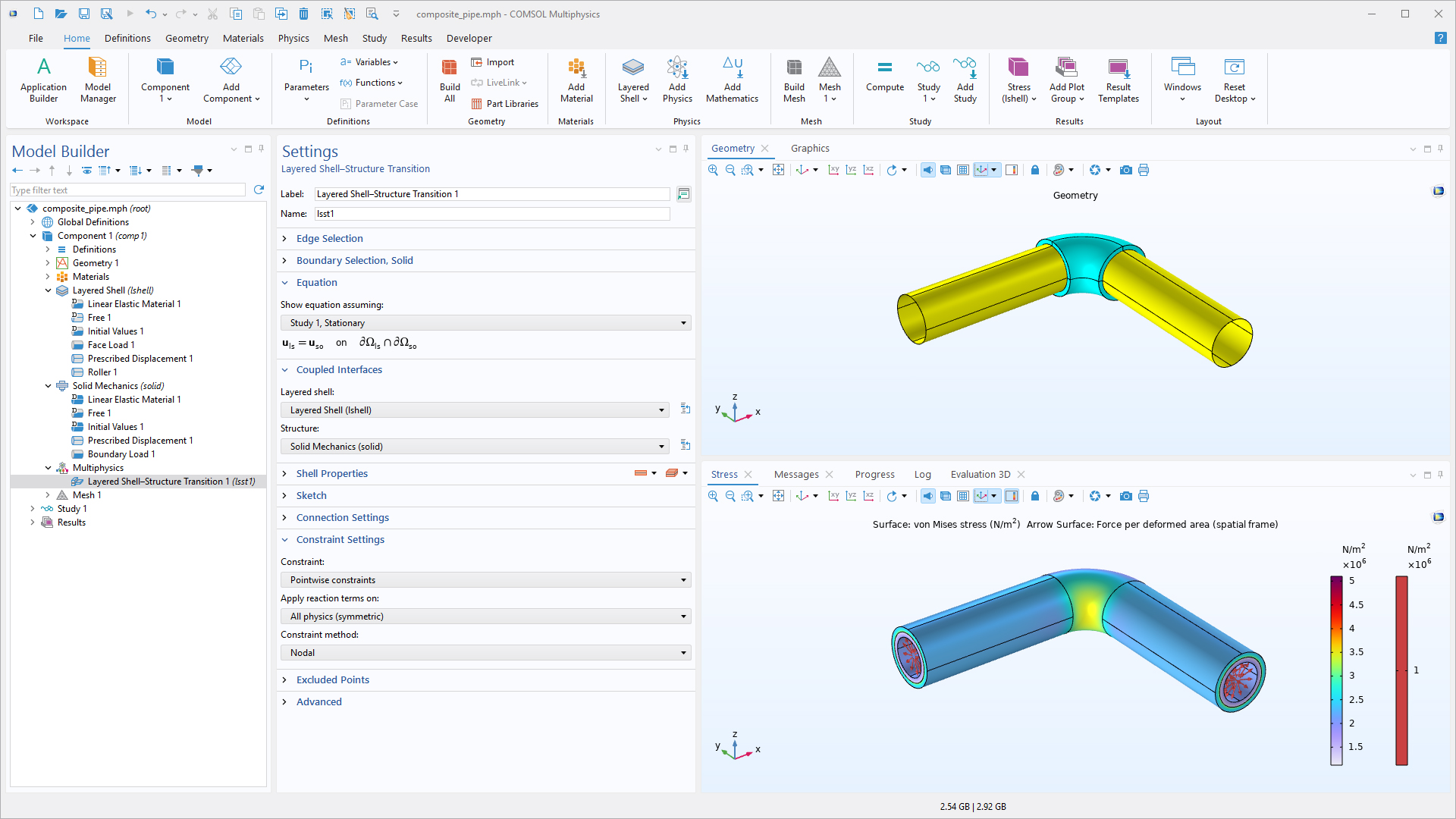
Miglioramenti all'accoppiamento multifisico Layered Shell–Structure Transition
Sono stati apportati due miglioramenti principali all'accoppiamento multifisico Layered Shell–Structure Transition: la formulazione per i collegamenti strutturali è stata migliorata e il metodo di vincolo predefinito è ora impostato su Nodal.
Nuovo tutorial
La versione 6.4 di COMSOL Multiphysics® introduce un nuovo modello di verifica nel Composite Materials Module.
Parametric Study on Cross-Ply Laminate Failure
parametric_study_on_crossply_laminate_failure
Download da Application Gallery