Heat Transfer Module Updates
For users of the Heat Transfer Module, COMSOL Multiphysics® version 6.0 brings improved computational performance and stored view factors for surface-to-surface radiation, a new packed beds interface to model multiscale heat transfer in pellet beds, and several new tutorial models. Read more about the Heat Transfer Module updates below.
Unprecedented Improvement of Surface-to-Surface Radiation Computational Performance
A new formulation of the radiosity equation has been implemented for the Surface-to-Surface Radiation interface, in particular when the hemicube method is used. Combined with improved solver settings, this provides a factor of 10 times decrease of the CPU time and memory requirements for these computations. These performance improvements come with no sacrifice in accuracy compared to previous versions. Furthermore, the reduced memory requirements make it practical to analyze significantly larger structures. This is particularly important for situations with large temperature differences, high surface emissivity, or small amounts of heat transfer by conduction and convection.
You can view this new feature in the new Heat Transfer in a Room with a Stove model and the following existing models:
- cavity_radiation
- chip_cooling
- heat_sink_surface_radiation
- inline_induction_heater
- light_bulb
- parallel_plates_diffuse_specular_ray_shooting
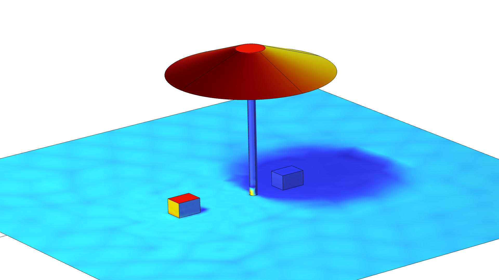
- parasol
- potcore_inductor
- thermal_annealing
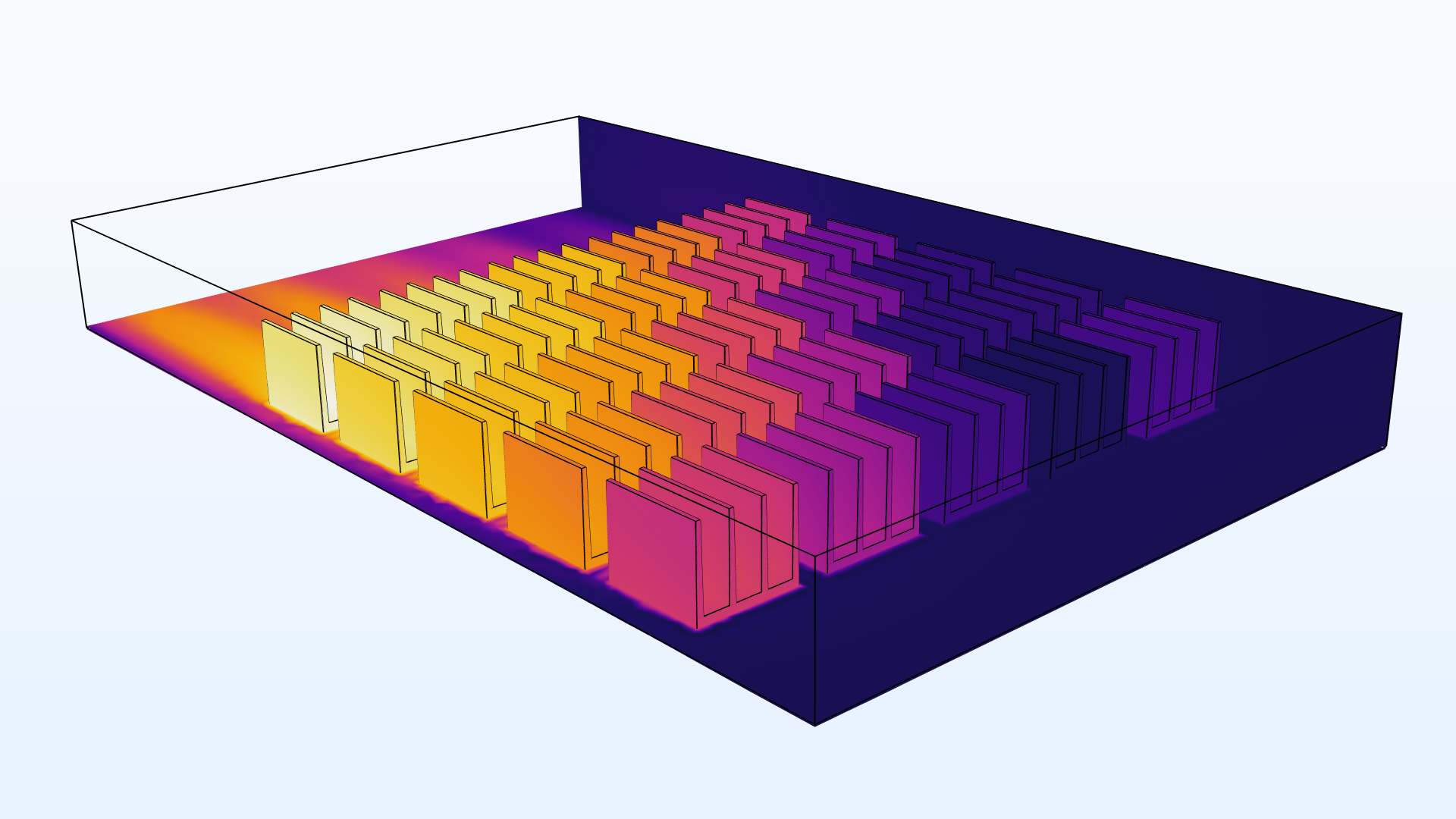
- tpv_cell
- view_factor
- petzval_lens_stop_analysis_with_surface_-_to_-_surface_radiation
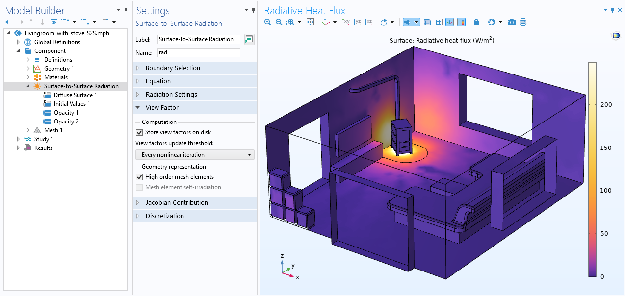
Disk Storage of View Factor for Surface-to-Surface Radiation
The Surface-to-Surface Radiation interface now includes a new Store view factors on disk option. When this option is checked, the view factors are stored in the model after being calculated once. Therefore, they do not need to be recalculated, provided that the mesh is unchanged and the changes in the radiation configuration are below the threshold defined by the user. This saves significant computational time for cases where the view factor calculation is demanding, typically with specular or semitransparent surfaces, which includes applications with polished and textured metal walls.
You can view this new feature in the new Heat Transfer in a Room with a Stove model and the following existing models:
- cavity_radiation
- chip_cooling
- heat_sink_surface_radiation
- inline_induction_heater
- light_bulb
- parallel_plates_diffuse_specular_ray_shooting
- parasol
- potcore_inductor
- thermal_annealing
- tpv_cell
- view_factor
- petzval_lens_stop_analysis_with_surface_-_to_-_surface_radiation
Surface-to-Surface Radiation Improvements
In addition to the computational improvements and the possibility to store the view factors on disk as described above, COMSOL Multiphysics® version 6.0 introduces simplifications in the user interface. This includes controlling the view factor update when used with moving mesh, the definition of different properties on two sides of a shell, and editing the unit of spectral band endpoints. The Prescribed Radiosity feature has support for Directional dependence when the Surface-to-surface radiation method is set to Ray shooting.
An important improvement is that the radiosity is now assumed to be discontinuous by default on edges. This is physically motivated and can be illustrated when only one of two faces connected by an edge is exposed to solar radiation. This improves the robustness from a computation point of view. Finally, the ray-shooting method for the view factor computation is now available for 2D-axisymmetric geometries.
You can view this new feature in the new Heat Transfer in a Room with a Stove model and the following existing models:
- cavity_radiation
- chip_cooling
- heat_sink_surface_radiation
- inline_induction_heater
- light_bulb
- parallel_plates_diffuse_specular_ray_shooting
- parasol
- potcore_inductor
- thermal_annealing
- tpv_cell
- view_factor
- petzval_lens_stop_analysis_with_surface_-_to_-_surface_radiation
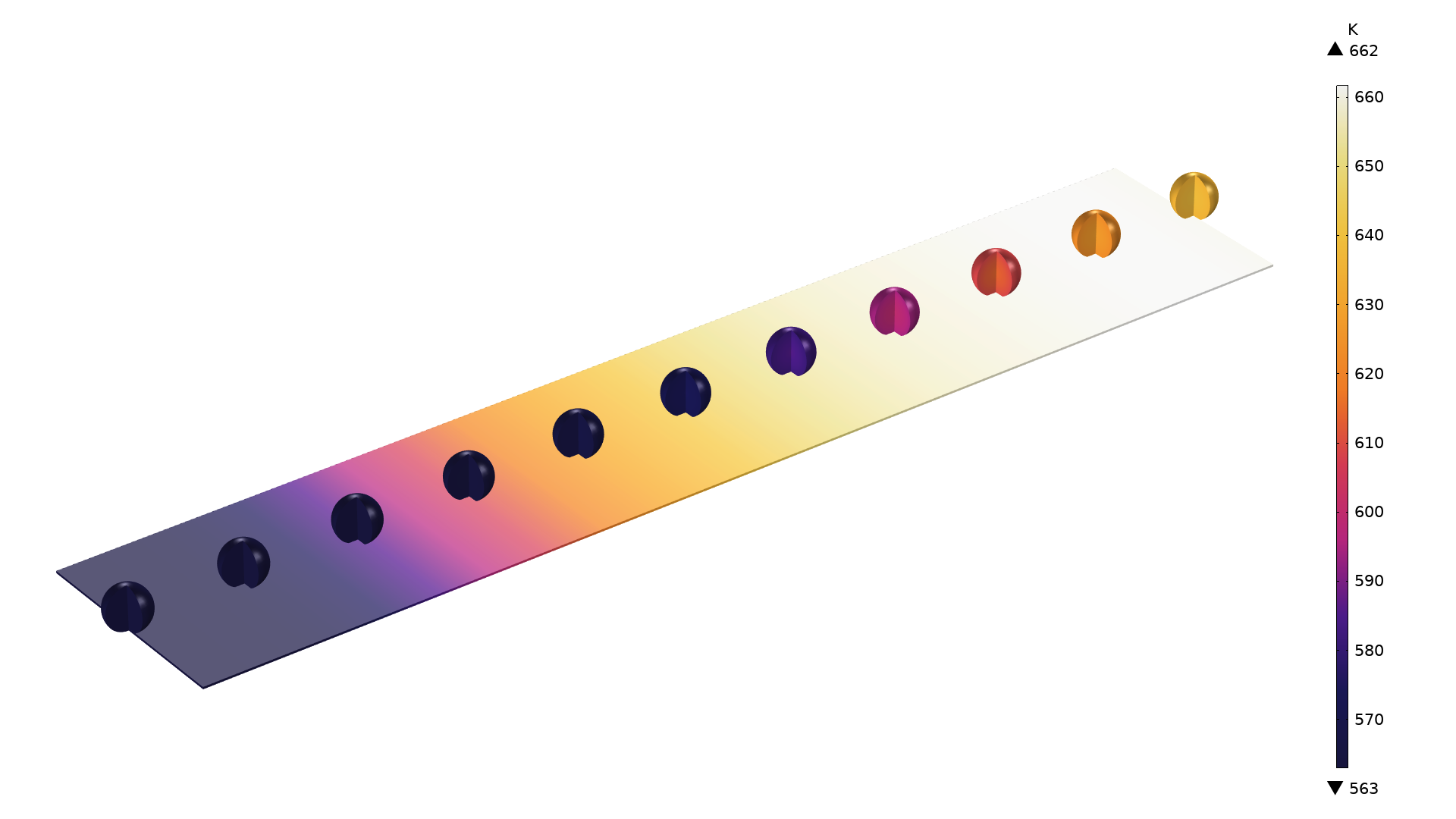
Multiscale Heat Transfer in Pellet Beds
A new Heat Transfer in Packed Beds interface has been added to model heat transfer in pellet beds. The pellet bed is represented as a porous medium made up of fluid and pellets. The pellets are modeled as spherical homogenized porous particles in which the temperature varies radially. The temperature distribution in the pellets is computed for every position in the packed bed. It is coupled to the temperature in the surrounding fluid through an interstitial heat flux between the pellets' surfaces and the fluid.
The new functionality is useful for modeling heat in packed bed thermal energy storage systems or the chemical reaction in a packed bed when coupled with the corresponding feature for transport of chemical species. View this new feature in the new Packed Bed Thermal Energy Storage System tutorial model.

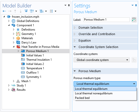
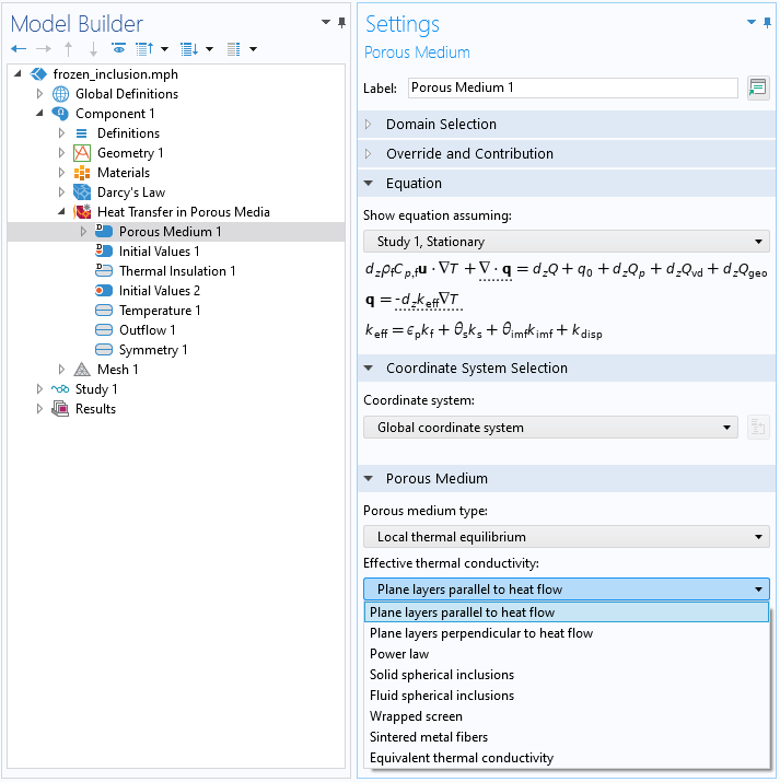
Heat Transfer in Porous Media
The heat transfer in porous media functionality has been revamped to make it more user friendly. A new Porous Media physics area is now available under the Heat Transfer branch and includes the Heat Transfer in Porous Media, Local Thermal Nonequilibrium, and Heat Transfer in Packed Bed interfaces. All of these interfaces are similar in function, the difference being that the default Porous Medium node within all these interfaces has one of three options selected: Local thermal equilibrium, Local thermal nonequilibrium, or Packed bed. The latter option has been described above. The Local Thermal Nonequilibrium interface, which replaced the multiphysics coupling, corresponds to a two-temperature model: one for the fluid phase and one for the solid phase. Typical applications can involve rapid heating or cooling of a porous medium due to strong convection in the liquid phase and high conduction in the solid phase like in metal foams. When the Local Thermal Equilibrium interface is selected, new averaging options are available to define the effective thermal conductivity depending on the porous medium configuration.
In addition, postprocessing variables are available in a unified way for homogenized quantities for the three types of porous media. View the new porous media additions in these existing tutorial models:
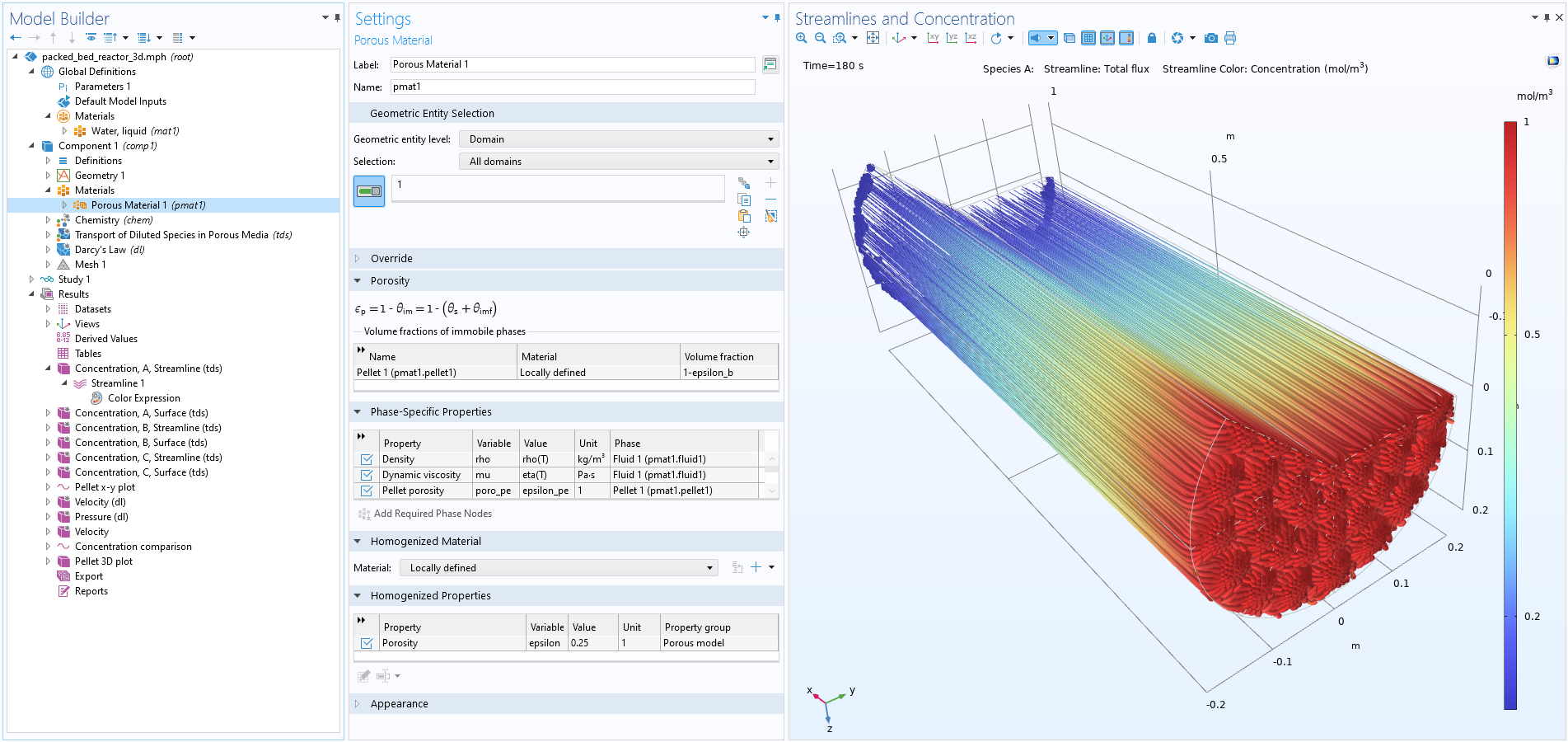
Greatly Improved Handling of Porous Materials
Porous materials are now defined in the Phase-Specific Properties table in the Porous Material node. In addition, subnodes may be added for the solid and fluid features where several subnodes may be defined for each phase. This allows for the use of one and the same porous material for fluid flow, chemical species transport, and heat transfer without having to duplicate material properties and settings.
Nonisothermal Reacting Flow
There are now Nonisothermal Reacting Flow multiphysics interfaces that automatically set up nonisothermal reacting flow models. The Reacting Flow multiphysics coupling now includes the option to couple the Chemistry and Heat Transfer interfaces. Using this coupling, the cross-contributions between heat and species equations like enthalpy of phase change or the enthalpy diffusion term are included in the model. The temperature, pressure, and concentration dependence of different quantities and material properties are also automatically accounted for, making it possible to perform heat and energy balance using the corresponding predefined variables. View this new feature in the existing Dissociation in a Tubular Reactor tutorial model.
Velocity at Walls for Moisture Evaporation and Condensation
Surface reactions, such as evaporation or condensation, result in a net vapor flux between the surface and surrounding domain. This type of reaction corresponds to an effective moist air velocity at the domain boundary, called the Stefan velocity. Whenever large evaporation rates are expected, the Stefan flow should be taken into account as it can be important in the overall behavior of the system. In the Moisture Flow multiphysics coupling, an Account for Stefan velocity at walls check box is now available when the Concentrated Species formulation is used in the Moisture Transport interface. This is recommended in evaporation and condensation applications when the temperature is high, typically above 50°C. You can see this feature in the new Modeling of Stefan Flow Due to Evaporation from a Water Surface tutorial model.
Moisture Transport Improvements
The Moisture Transport interfaces now provide a Periodic Condition feature that enables you to reduce the simulation domain for a periodic structure or to evaluate effective properties from a representative cell. In addition, the Hygroscopic Porous Media feature has been updated to match the classical design for features for porous materials. The variables for energy balance have been optimized for a much faster evaluation and new variables are now available to check the mass balance. You can see the moisture transport improvements in the new Drying of a Potato Sample tutorial model and these existing models:

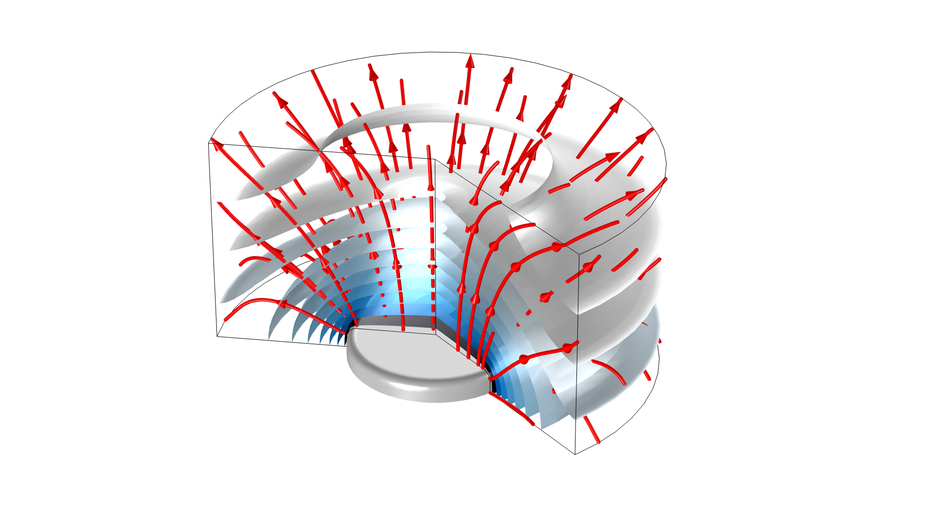
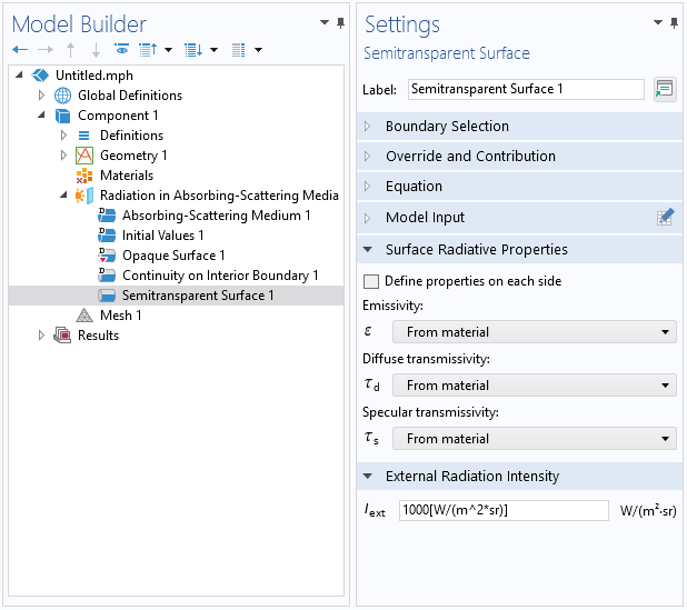
Semitransparent Boundary Condition for Radiation in Absorbing and Scattering Media
The new Semitransparent Surface feature is available in the Radiation in Absorbing and Scattering Media interface. On exterior boundaries, you can specify an external radiation intensity and account for the part of the incoming intensity that is diffusively or specularly transmitted through the surface. On interior boundaries, the radiation intensities on both sides of the surface are considered. This boundary condition is especially useful for modeling incident radiation coming from a transparent medium on a semitransparent media sample, for example, modeling the characterization of radiative properties of participating media.
Heat Transfer in Layered Shell Curvature
The formulation to describe heat transfer in shells has been improved to account for the effect of the surface curvature on the layers' dimensions. In the case of highly curved layered shells, the area and volume of the inner surface and layer, respectively, are very different from the ones of the outer layer. With this improvement, the Layered Shell interface under the Structural Mechanics branch can accurately handle thick and curved surfaces. View this update in the new Coupling a Finite Element Model for Heat Transfer with a Lumped Thermal System tutorial model.
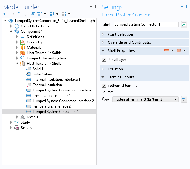
Connector Between Lumped Thermal Systems and Shells
The new Lumped System Connector and Lumped System Connector, Interface conditions have been introduced to connect a lumped thermal system to a shell through the layer side or surface, respectively. In the connector feature, you can simply select any of the External terminal options available in the Source, Pext combo box to connect the shell entity with the corresponding external terminal in the lumped thermal system interface. You can see this feature in the new Coupling a Finite Element Model for Heat Transfer with a Lumped Thermal System tutorial model.
Phase Change Interface
A new Phase Change Interface, Exterior boundary condition has been added to apply on exterior boundaries. This is especially useful when one of the phases is gaseous and escapes easily. The existing Phase Change Interface boundary condition is now only applicable for interior boundaries. The Phase Change Interface and Phase Change Interface, Exterior boundary conditions now account for the casting velocity of solids to define the velocity of the fluid phase at the interface. View this new feature in the new Continuous Casting — Arbitrary Lagrangian–Eulerian Method tutorial model and the existing Freeze Drying and Tin Melting Front models.
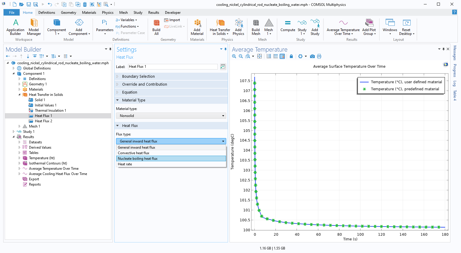
Heat Flux Option to Model Nucleate Boiling
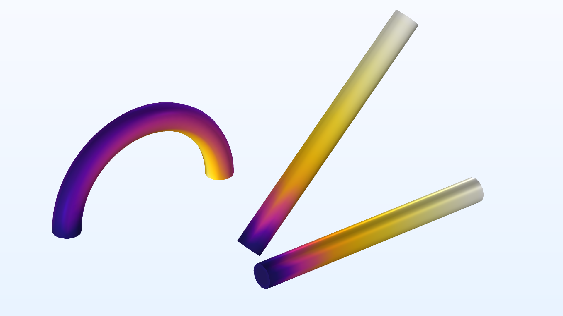
Nucleate boiling is a regime of pool boiling where the heat transfer coefficient becomes very large. It is characterized by a temperature of the surface higher than the saturation temperature of the fluid, and by the generation of vapor at a number of favored spots on the surface called nucleation sites. Nucleate boiling is used in different engineering processes because it achieves high heat transfer coefficients with moderate temperature gradients. A new Nucleate boiling heat flux is now available as a predefined option in the Heat Flux node. The implementation is based on the Rohsenow correlation and the coefficients needed to define the correlation are predefined for some liquid and surfaces types. Alternatively, it is possible to enter user-defined coefficients. You can see this new update in the new Cooling of a Nickel Cylindrical Rod with Nucleate Boiling of Water tutorial model.
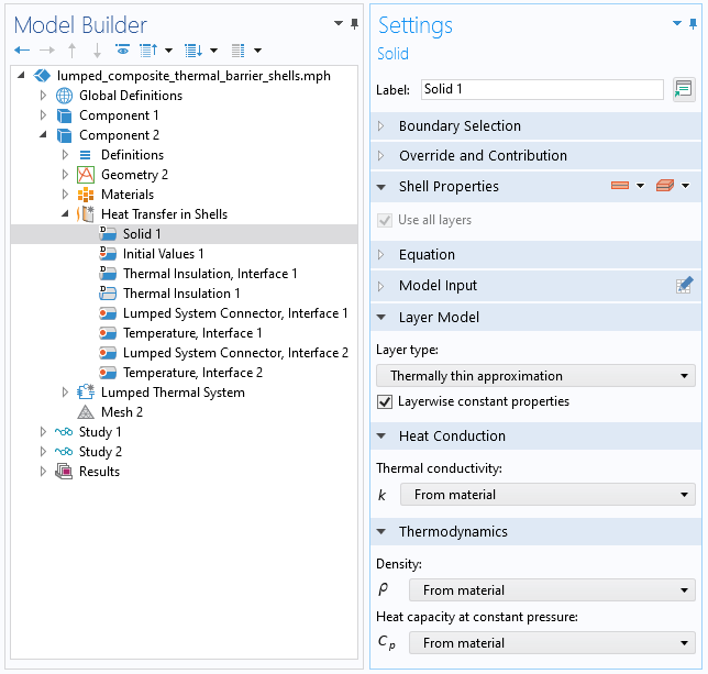
Heat Transfer in Thin Structures Improvements
Several changes have been introduced to optimize computational performance. From a modeling point of view, a new Symmetry boundary condition is available for thin structures (thin layers, films, and fractures) to reduce the computational cost when the geometry and operating conditions are symmetric. From a numerical point of view, a new Layerwise constant properties option is available when the Layer type is set to Thermally thin approximation and is active by default for thermally thin structures. By assuming that the material properties are constant per layer, but still changing with layers or with the layer temperature, a significant speedup is obtained, especially when the number of mesh elements used to discretize the layered material is important. You can see these new improvements in two new tutorial models, Lumped Composite Thermal Barrier with Shells and Lumped Thermoelectric Module with PID Control as well these existing models:
- aluminum_extrusion_fsi
- composite_thermal_barrier
- concentric_tube_heat_exchanger
- copper_layer
- disk_stack_heat_sink
- double_pipe_heat_exchanger
- electronic_enclosure_cooling
- finned_pipe
- heating_circuit
- isothermal_box
- parasol
- shell_and_tube_heat_exchanger
- shell_conduction
- surface_mount_package
- vacuum_flask

Marangoni Effect
The Marangoni effect occurs when there is a gradient of surface tension at the interface between two phases. The gradient of surface tension may originate from a concentration gradient or from a temperature gradient. In the case of temperature dependence, the Marangoni effect is also called thermo-capillary convection. The Marangoni Effect multiphysics coupling has been updated to account for both the tangential and normal effects of the surface tension and the contact angle can now be defined. Finally, the new formulation results in improved computational performance. The Marangoni effect is of primary importance in the fields of welding, crystal growth, and electron beam melting of metals. The existing Marangoni Effect tutorial model demonstrates these new updates.
Thermal Conductivity Model for Large Strains
A new Large Strain option has been added for the material deformation model in the Solid feature in the heat transfer interfaces. The purpose is to better capture the behavior of the thermal conductivity in situations such as when large plastic deformations occur during material processing.
New Tutorial Models
COMSOL Multiphysics® version 6.0 brings several new tutorial models to the Heat Transfer Module.
Packed Bed Thermal Energy Storage System
Application Library Title:
packed_bed_thermal_energy_storage_system
Download from the Application Gallery
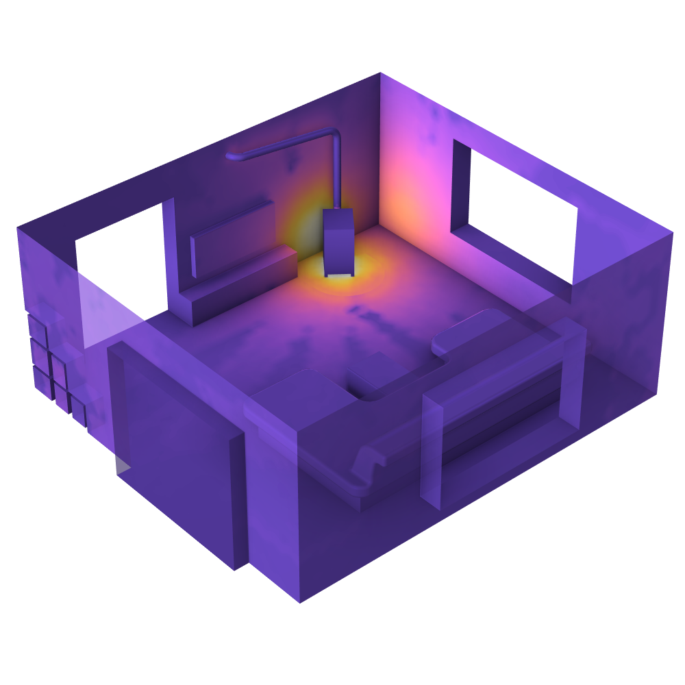
Heat Transfer in a Room with a Stove
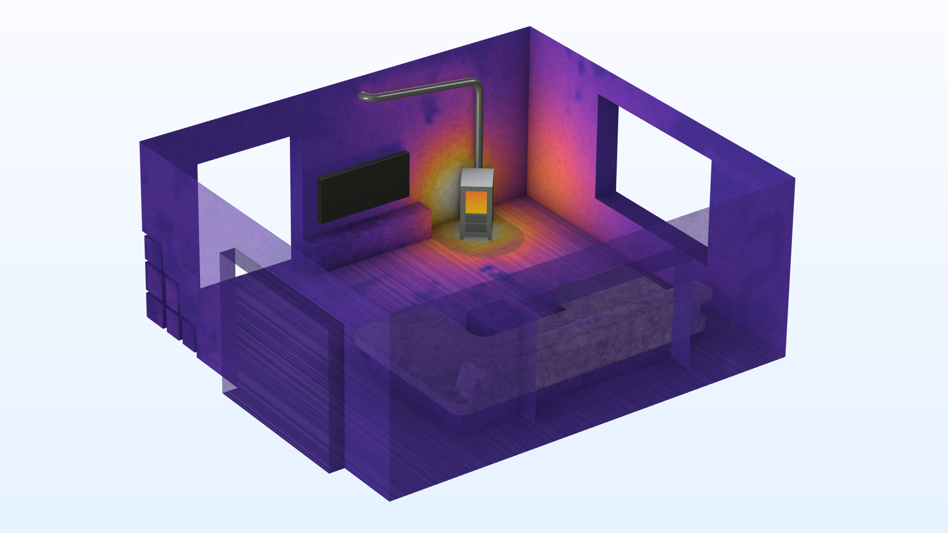
Application Library Title:
livingroom_with_stove_s2s
Download from the Application Gallery
Domestic Oven

Application Library Title:
domestic_oven
Download from the Application Gallery
Lumped Thermoelectric Module with PID Control

Application Library Title:
tec_pid_2
Download from Application Gallery
Glass Fiber Drawing Process

Application Library Title:
glass_fiber_drawing
Download from the Application Gallery
Continuous Casting — Arbitrary Lagrangian–Eulerian Method

Application Library Title:
continuous_casting_ale
Download from the Application Gallery
Lumped Composite Thermal Barrier with Shells
Application Library Title:
lumped_composite_thermal_barrier_shells
Download from the Application Gallery
Bulk Temperature Evaluation
Application Library Title:
bulk_temperature_3d
Download from the Application Gallery
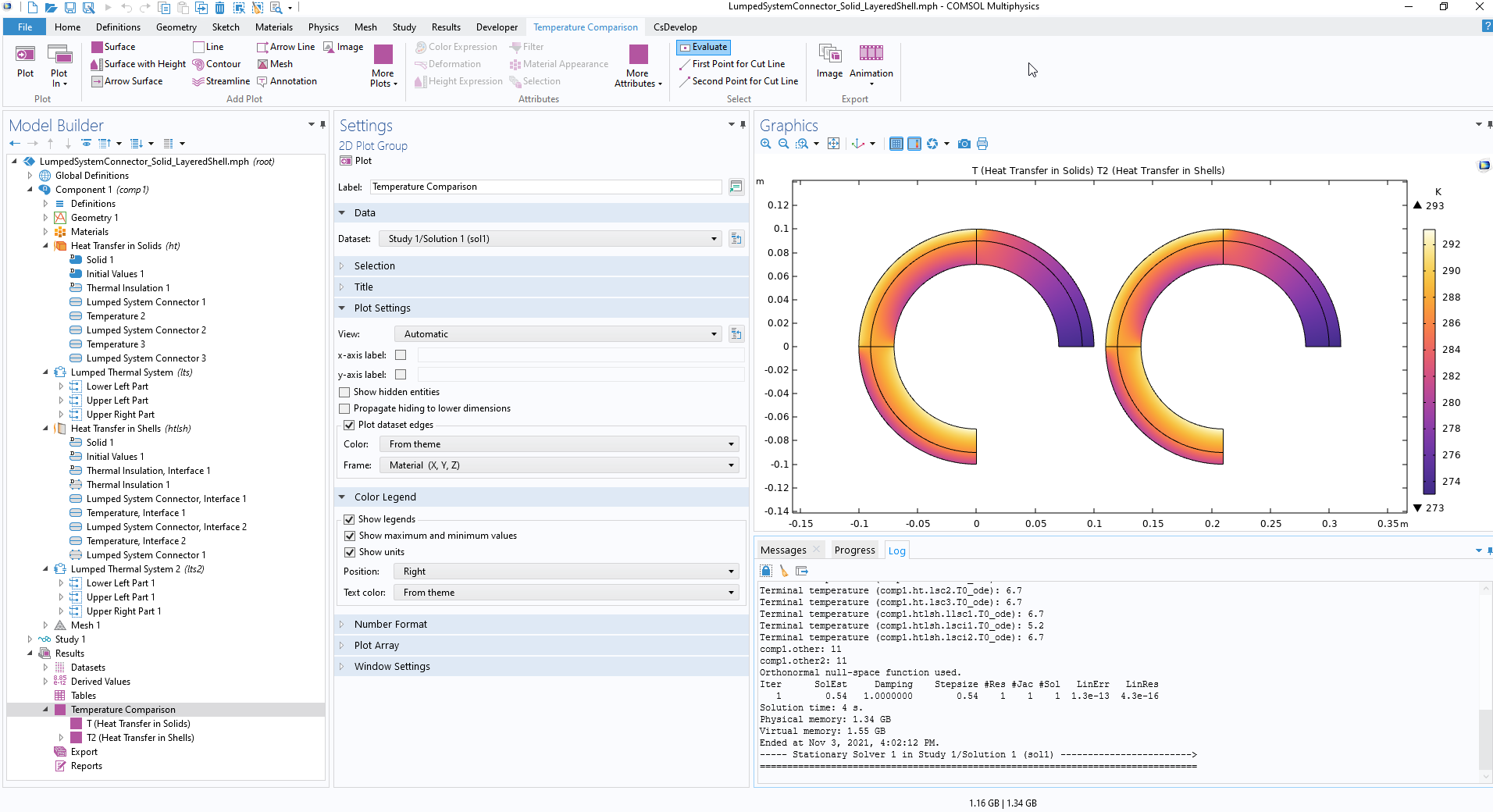
Coupling a Finite Element Model for Heat Transfer with a Lumped Thermal System
Application Library Title:
lumpedsystemconnector_solid_layeredshell
Download from the Application Gallery
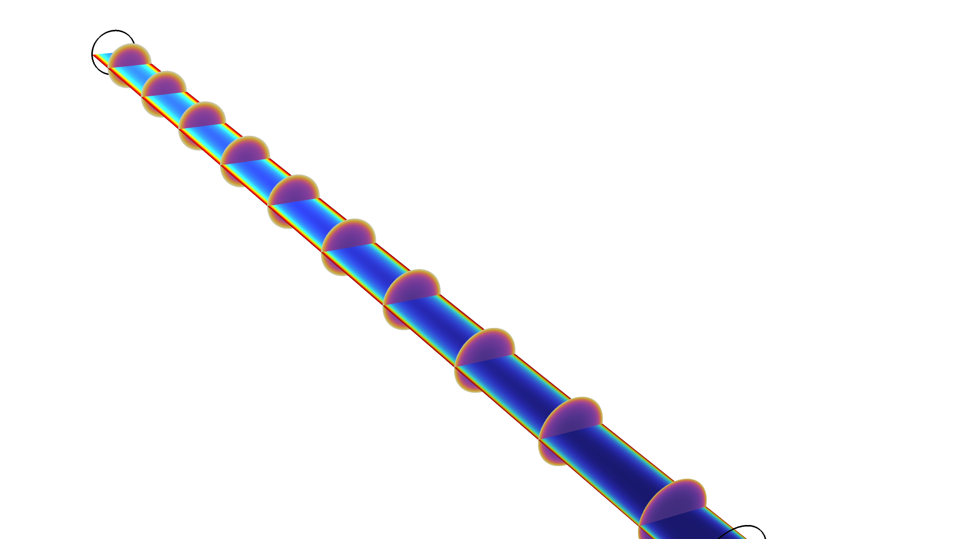
Isothermal Spherical Droplet Evaporation
Surface mesh quality as the droplet shrinks due to evaporation. This model demonstrates how to model phase transition by a moving exterior boundary condition using the arbitrary Lagrangian–Eulerian method.
Application Library Title:
isothermal_spherical_droplet_evaporation
Download from the Application Gallery
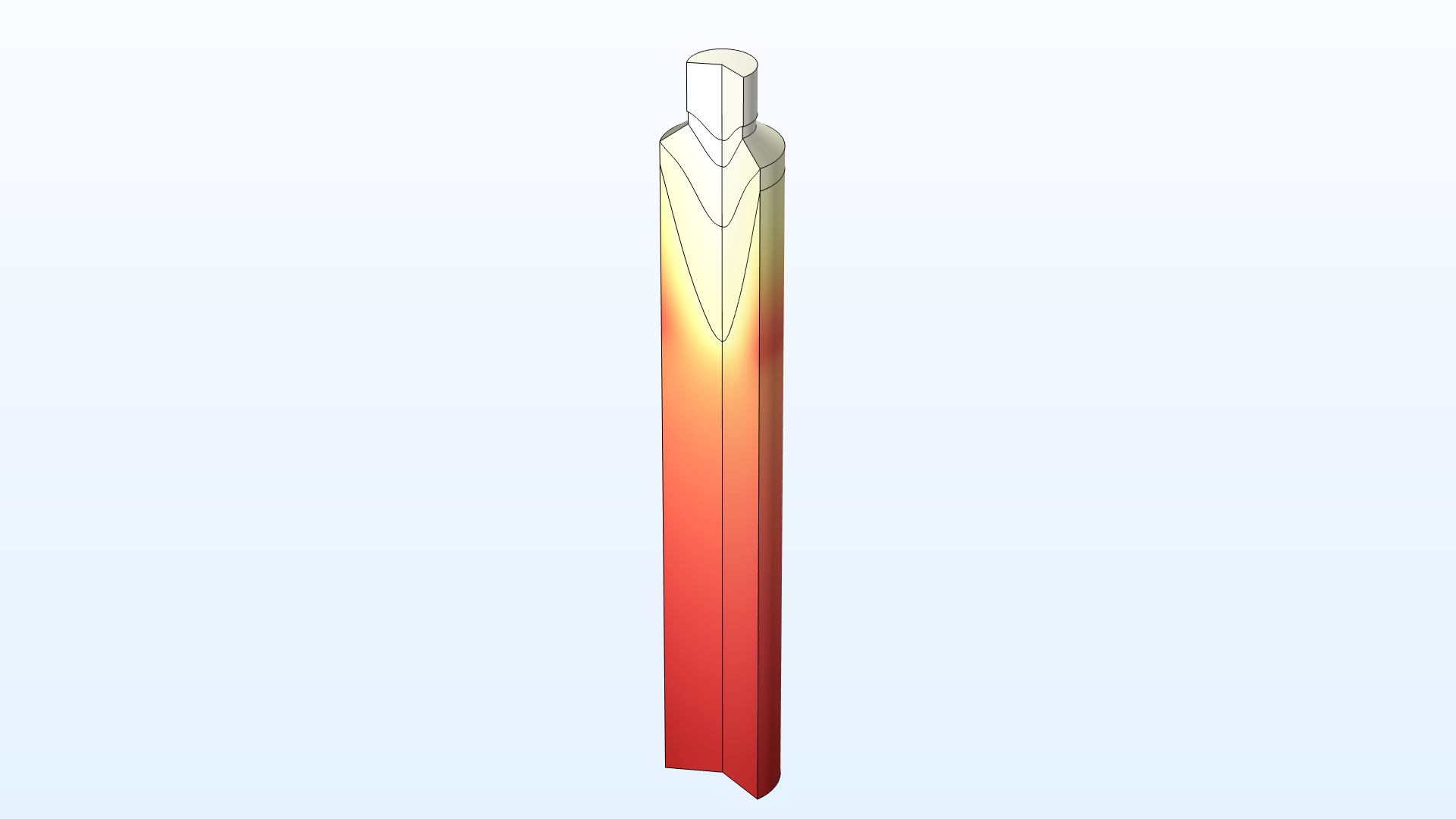
Cooling of a Nickel Cylindrical Rod with Nucleate Boiling of Water
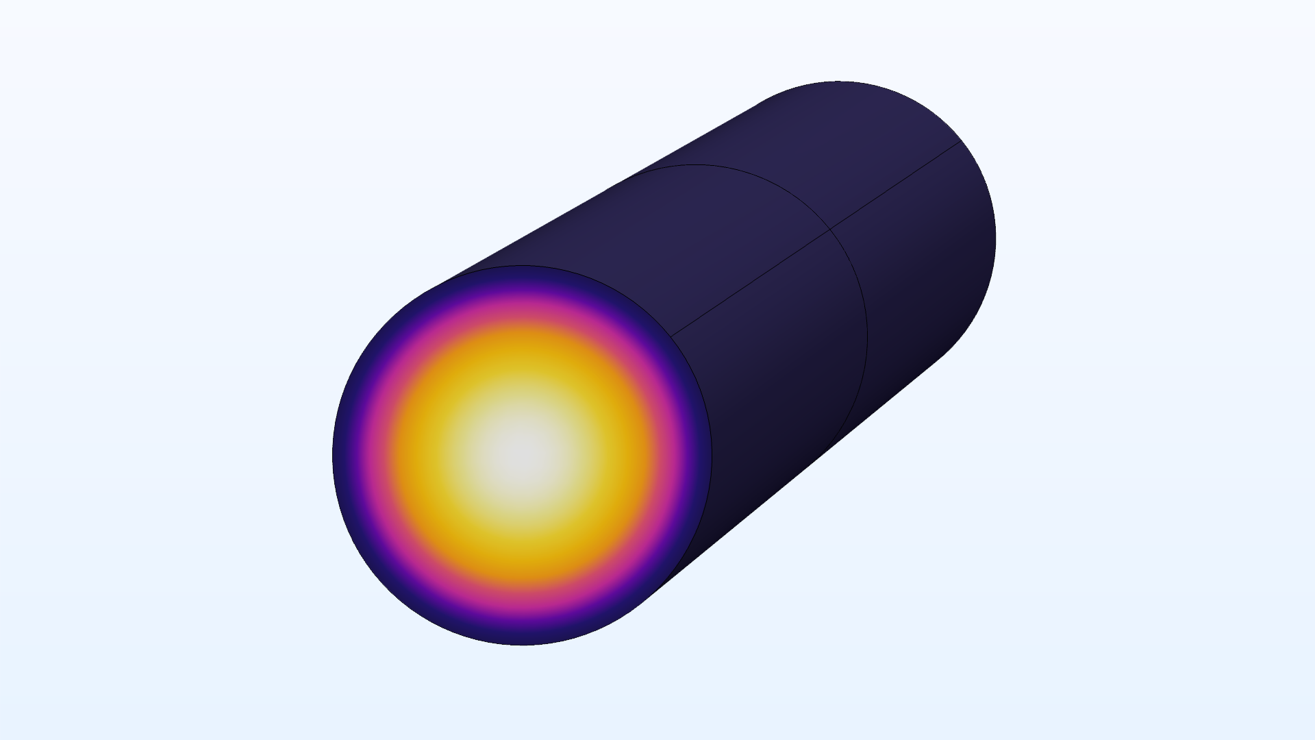
Application Library Title:
cooling_nickel_cylindrical_rod_nucleate_boiling_water
Download from the Application Gallery
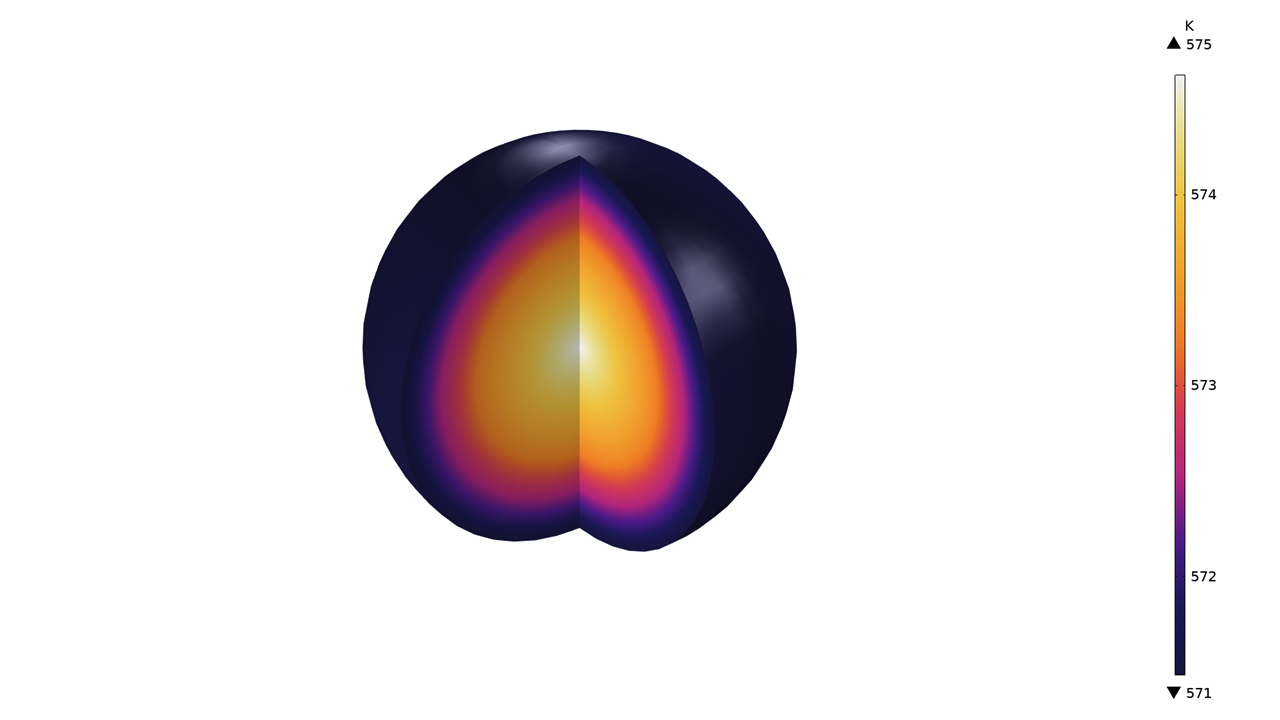
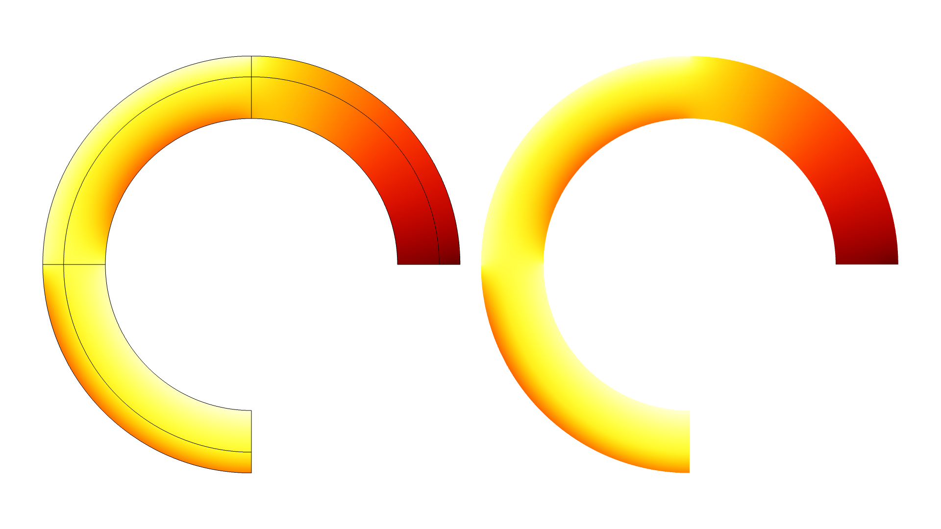
Averaging Models for Effective Thermal Conductivity in Porous Media
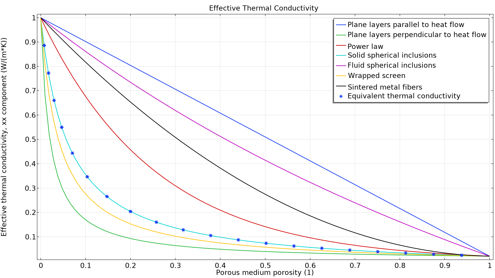
Application Library Title:
effective_thermal_conductivity_porous_media
Download from the Application Gallery