

For those designing process equipment with conventional centrifugal pumps, rotating conical (or cone) micropumps may provide a simpler alternative. However, the performance of rotating cone micropumps needs further analysis, which can be difficult to achieve with only trial-and-error empirical studies. To solve this issue, researchers used the COMSOL Multiphysics® software to develop a realistic model for analyzing the fluid dynamics and performance of a rotating cone micropump. Here, we discuss their research and results.
Rotating Cone Micropumps: A Simple Alternative to Centrifugal Pumps
One way to simplify the designs of key process equipment, such as rotating packed bed reactors and centrifugal disc atomizers, is to replace conventional centrifugal pumps with a less complicated alternative: rotating cone micropumps.
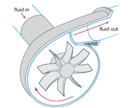
A conventional centrifugal pump (left) and rotating cone micropump (right). Images by A. Uchagawkar, M. Vasilev, and P. Mills and taken from their COMSOL Conference 2015 Boston presentation.
Before they can be used as replacements, rotating cone micropumps need further analysis. In particular, research on the velocity profiles over the rotating conical surfaces is quite important in process manufacturing industries. Such studies show that fluid velocity distributions greatly affect the efficiency of process equipment.
To fill this research gap, a team from Texas A&M University used COMSOL Multiphysics CFD simulations to accurately investigate the pump performance of a rotating cone micropump — a more efficient approach than trial-and-error empirical studies.
Modeling the Fluid Dynamics of a Rotating Cone Micropump in COMSOL Multiphysics®
The researchers used COMSOL Multiphysics to develop a realistic fluid dynamics model of a rotating cone micropump, which analyzes both laminar and turbulent flow regimes using the 3D transient Navier-Stokes equations.
The researchers looked at how the flow and pressure fields are affected by changing the micropump’s geometrical and operational parameters, including:
- Cone height and semiangle
- Ratio of outer to inner radius
- Angular rotational speed
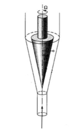
As seen in the following schematic, the model geometry is comprised of a vertical and rotating inner cone, rotating inner solid cone, and stationary outer cone. The fluid in this model is water.
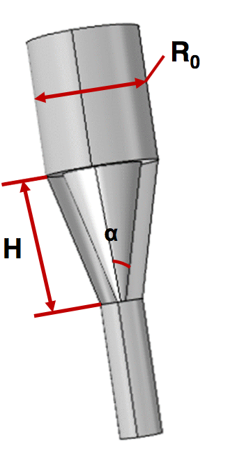
Rotating cone micropump geometry. Here, H is the height of the cone, α is the cone semiangle, and R0 is the upper radius. Image by A. Uchagawkar, M. Vasilev, and P. Mills and taken from their COMSOL Conference 2015 Boston presentation.
The research team used an unstructured mesh with tetrahedral elements and tested different element sizes to see how the number of elements (mesh resolution) affects the computation results. The results show that the computed pressure head varies to a very small extent with the number of elements (48,000; 92,000; and 124,000), indicating that the results are within the required accuracy for the lowest number of elements (48,000).
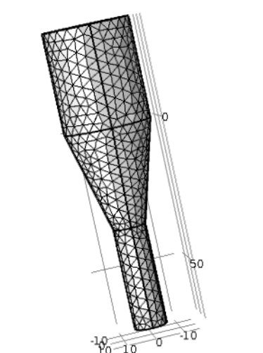
Tetrahedral mesh with 48,000 elements. Image by A. Uchagawkar, M. Vasilev, and P. Mills and taken from their COMSOL Conference 2015 Boston presentation.
To expand the reach of this study, the researchers created a dedicated user interface for running the model (an app) using the Application Builder in COMSOL Multiphysics. For more information about the researchers’ model and simulations, check out the full paper.
Analyzing the Performance of Rotating Cone Micropumps
Let’s go over a few of the research team’s results now, beginning with the fluid velocity and pressure profiles for rotating cone micropumps with two different cone semiangles. The plots below show that the velocity magnitude remains below 0.1, which for this system corresponds to a Reynolds number of around 1.5. Within this range of Reynolds numbers, viscous forces are the main driver of flow for micropumps. As for the velocity patterns, these switch from the axial direction at the inlet to the angular direction at the angled region. Upon leaving the cone’s angled region, the velocity transitions into a combination of angular and axial behavior.
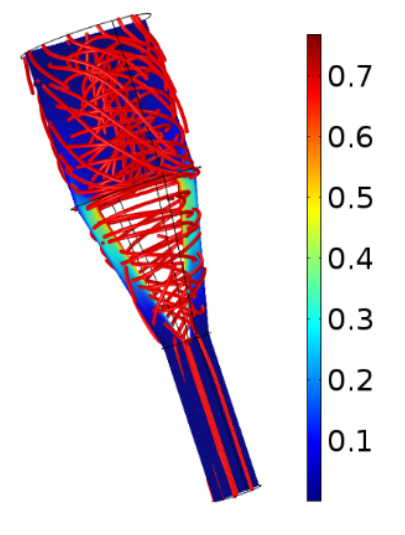
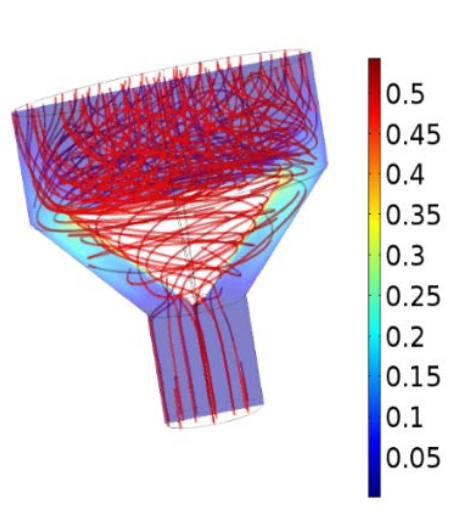
Velocity profiles for a rotating cone micropump with a semiangle of 12° (left) and 45° (right). Both cones give a volumetric flow rate of 1 ml/s. Images by A. Uchagawkar, M. Vasilev, and P. Mills and taken from their COMSOL Conference 2015 Boston paper.
Moving on to the corresponding fluid pressure profiles, these indicate that the micropump’s hydraulic head is a weak function of both the cone semiangle and rotating cone’s height. While the micropump head is greatly affected by the frequency of rotation, the hydrodynamic head remains below 135 Pa, even at the maximum rotational speed of 12,000 RPM.
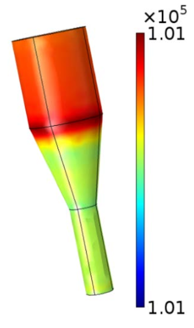
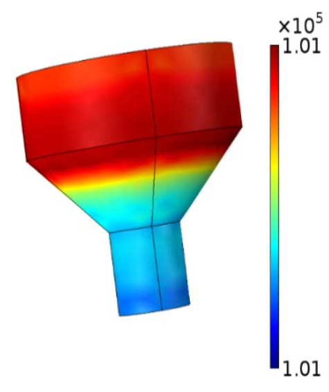
Fluid pressure profiles for a rotating cone micropump with a semiangle of 12° (left) and 45° (right). Both cones have a volumetric flow rate of 1 ml/s. Images by A. Uchagawkar, M. Vasilev, and P. Mills and taken from their COMSOL Conference 2015 Boston paper.
The researchers also predicted the head curve for various angular rotational speeds by repeatedly running the model for each volumetric flow rate and angular speed pair as well as calculating outlet pressure. The outlet pressure shows a near linear decrease with an increasing volumetric flow rate. The micropump head is also almost proportional to the square of the rotational speed.
Comparison of the micropump head with different RPM values. Image by A. Uchagawkar, M. Vasilev, and P. Mills and taken from their COMSOL Conference 2015 Boston paper.
Other factors, including the fluid’s viscosity and density, can also affect the pressure head that the rotating cone micropump produces. To demonstrate, two head curves for liquids with different viscosities and densities and the same operating conditions are compared below. Water, the more viscous and dense fluid, generates a larger pressure difference throughout the range of flow rates than the other fluid, diethyl ether. For conventional centrifugal pumps, the opposite is true. However, the pressure head behavior trends for water and diethyl ether are similar and agree with those for centrifugal pumps.
Comparison of pressure head curves for water and diethyl ether at 12,000 RPM. Image by A. Uchagawkar, M. Vasilev, and P. Mills and taken from their COMSOL Conference 2015 Boston paper.
Simulation Helps to Evaluate the Benefits and Uses of Rotating Cone Micropumps
Overall, rotating cone micropumps can create comparatively large throughputs, but the pressure heads that they create don’t compare to those of conventional centrifugal pumps. Therefore, this rotating cone micropump design is best suited for applications requiring small pressure heads like microprocess systems. In these cases, rotating cone micropumps are a good choice due to their simplicity and performance.
Moving forward, the team notes that they can optimize their rotating cone micropump design. By using CFD simulations, they can evaluate the effects of adding modifications to the cone head surface, such as spiral fins. These results can then be compared with empirical data.
Further Resources on CFD Simulation
- Get more details about the research: “Hydrodynamic Modeling of a Rotating Cone Pump Using COMSOL Multiphysics® Software“
- Watch an 18-minute archived webinar on CFD simulation
- Browse additional CFD blog posts:


Comments (0)