

Have you been interested in learning how to create fillets on 3D designs or how to generate shell approximations of imported geometric objects? The latest version of the COMSOL Multiphysics® software includes the new Design Module, which provides these and other tools for easier and more advanced geometric modeling. This optional add-on also includes interoperability tools for the import and export of CAD designs. Let’s take a look in more detail at what you can do with these new features.
Loft
The Loft operation comes in handy when Extrude or Sweep won’t do the job because they do not support multiple cross sections. You can create solid or surface objects from cross sections defined by a face or a profile curve. The profile can be closed or open. For start and end profiles, you can specify the direction of the loft in relation to the profile or adjacent faces. To further control the shape of the loft, you can include guide curves that connect the profiles.
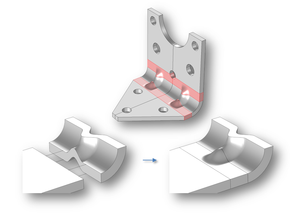
The highlighted regions of this bracket geometry are generated using the loft command by joining the two cross-sectional faces. The loft shape is controlled by guide curves and a setting that keeps the loft direction perpendicular to the profile faces.
Fillet and Chamfer
The Fillet and Chamfer operations do not need much introduction; they do exactly what we expect them to do — now in 3D. You can create fillets and chamfers with constant radii on edges on 3D solids and surfaces. The fillet or chamfer can automatically propagate to edges that are tangent to the selected edges, which makes the selection of the input entities quite easy.
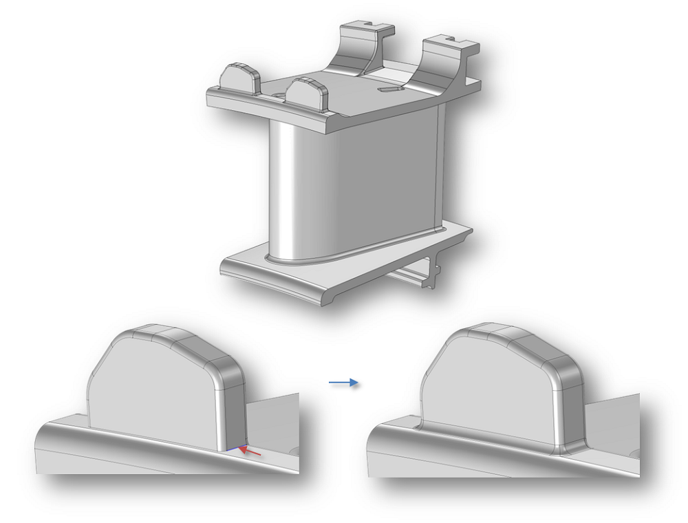
The fillets on this turbine stator geometry are created using the Design Module. On the enlarged detail (bottom of the image), the fillet propagates to edges tangent to the selected edge (marked with a red arrow). The tool automatically handles the overflow of the fillet into the adjacent fillet in the front.
Midsurface and Thicken
Setting up a finite element model on the midsurface of a solid object is an analysis technique that is used quite often for parts with a very thin geometry (e.g., something made out of sheet metal). The Design Module enables the calculation of the midsurface of a solid object. The inverse of the Midsurface operation, called thicken, allows you to add material to a surface to convert it to a solid. You can add the thickness in the default normal direction to the surface or specify a direction. The Thicken operation can be symmetric, where an equal amount of volume is added on each side of the surface. It can also be asymmetric, which allows you to specify the thickness on each side.
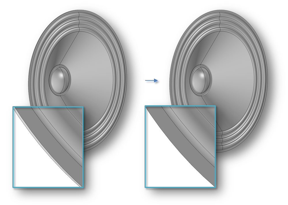
The geometry of this imported speaker cone is reduced from a solid to a surface object by the Midsurface tool.
CAD Interoperability
All of the newly added geometric tools are fully integrated into the parametric geometry modeling framework in the COMSOL Multiphysics® simulation software. You can use parameter-based expressions in the settings for the operations and thereby control the geometry from the parametric solver or an optimization solver (requires the Optimization Module).
The Design Module also includes all the functionality of the CAD Import Module, such as the file import of widely used CAD file formats and tools to repair and defeature imported geometry. To share your designs, you can export to the Parasolid® software and ACIS® software formats. Read more about the functionality of the Design Module here.
Next Steps
Now that we have introduced you to the Design Module, we will continue with additional blog posts focusing on specific aspects. Stay tuned.
In the meantime, check out the product page for the Design Module.
ACIS is a registered trademark of Spatial Corporation.
Parasolid is a registered trademark of Siemens Product Lifecycle Management Software Inc. or its subsidiaries in the United States and in other countries.


Comments (3)
Brad Cox
December 17, 2014Informative post .Thanks for sharing .
Oscar Diaz
September 30, 2016hi Lorant,
I checked on https://www.comsol.com/design-module, and it says nothing about how to loft a surface to create a 3D object. Neither is any info available in the DesignModuleUsersGuide nor COMSOL_ReferenceManual nor webpage support/videos/etc
I know comsol CAD modeller is basic and its main goal is not to include all functions available in regular 3D CAD software, but definitely it should provide a proper help/guidance on the newest modelling featured tools.
It would be great that a more detailed blog entrance is written regarding these tools.
Lorant Olasz
October 13, 2016Hi Oscar,
Thanks for the feedback, we will definitely think about this for future blog posts and videos.
In the current COMSOL version, 5.2a, the Introduction to Design Module manual includes an example describing the loft operation starting on page 6. More details about the options for the operation can be found in the Design Module User’s Guide, on page 37, and the corresponding API command is described on page 78 of the same manual.
You are also welcome to contact support with any questions.
Best regards,
Lorant