
Efficiently Verify Electric Fields Outside Electrical Installations with Apps

Electrical installations must often adhere to requirements for the maximum electric field levels in their surrounding area. Electric fields that are too high can be harmful to both operators and the general public. Simulation is typically used to verify that these levels meet the requirements, otherwise significant redesigns may be needed much later on. The Application Builder enables design engineers to perform verification studies earlier in the process.
Safety Requirements for Electrical Installations
Electrical installations, such as substations and capacitor banks, play an important role in delivering the right amount of power to homes and businesses. But just as important as the ability of this equipment to supply such power is the overall safety of the system. For instance, when electric fields are too high in the area surrounding an electrical installation, they can pose potential health risks for the operators of the equipment as well as the general public. To this end, there are requirements that exist with regards to the maximum electric fields allowed outside the installation.
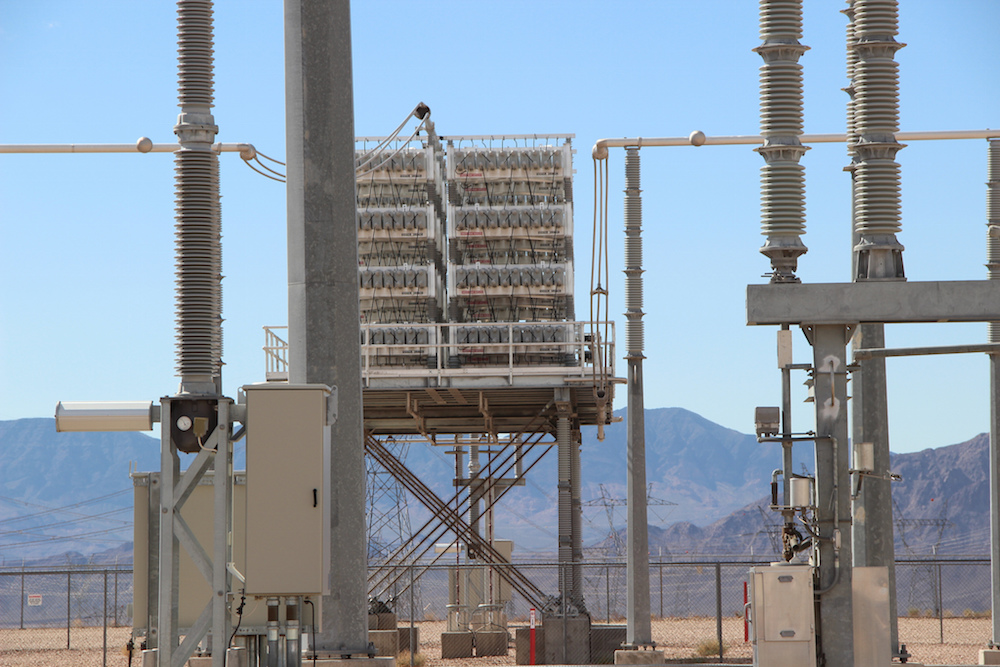
Electric fields outside electrical installations, like the capacitor bank shown above, are important considerations in the design of these systems. Image by Western Area Power. Licensed under CC BY 2.0, via Flickr Creative Commons.
Take the ICNIRP guidelines, for example. The focus of these requirements is to limit exposure to low-frequency electric fields, which are typically 50 to 60 Hz. Within these guidelines, as is typically the case, the maximum electric field is specified in two levels: one for authorized personnel and another for the general public. At 50 Hz, the general public can be exposed to a maximum of 5 kV/m, while personnel are allowed a higher exposure of 10 kV/m.
Simulation is the primary method used to verify that electrical installations meet these low-frequency requirements as well as those specified by customers. For simulation experts, performing such studies is a straightforward process, but these experts may not always be available to address simulation requests right away. This delay can result in the need for significant redesigns at a much later stage in the process.
By creating an easy-to-use app with the Application Builder, a built-in tool in the COMSOL Multiphysics® software, simulation experts can enable design engineers to verify electric field levels outside electrical installations on their own. Nils Lavesson, a principal scientist at ABB, built a simulation app in an effort to do just that.
Simplifying the Geometry of an Electrical Installation
When describing the geometry of an installation, one of the most practical problems that simulation engineers face is balancing the level of detail needed for accuracy with the level of simplification for efficiency. Designs like the ABB capacitor bank, shown below, are typically available as CAD drawings that can be imported into COMSOL Multiphysics. But these drawings are often quite detailed and require extensive simplification before they can be used in a simulation.
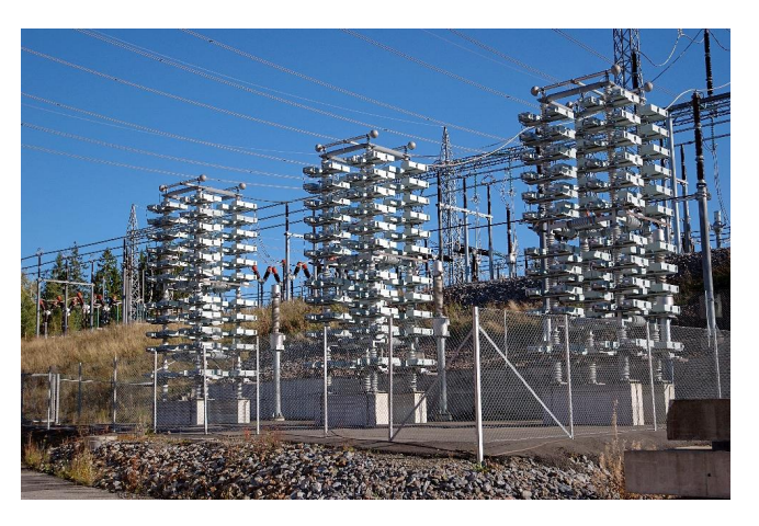
An ABB capacitor bank. Image by ABB.
As Lavesson was interested in the electric field significantly far away from the active parts, he opted to take the most common approach: creating a 3D CAD geometry based on the CAD drawing. In this geometry, simplified geometric shapes represent the electrical components. This usually provides a good degree of accuracy with regards to the calculated fields of interest. A typical geometry includes multiple components that are connected to different phases, with one or two fences surrounding it. This approach is useful for running simulations, but there’s a great deal of manual work that’s needed to set up the geometry. To automate this process, further simplifications are needed.
Lavesson chose to use a 2D axisymmetric geometry, which only considers one of the platforms connected to one phase. While this method may sound restrictive, it is sufficient to obtain a reasonable approximation for the final value. Most real cases involve three phases, but one of these phases is often dominant. Additional phases cause screening of the field, which makes approximating the problem with one phase a conservative approach. (We describe this in more detail in a previous blog post.)
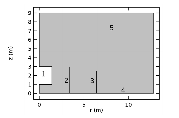
A simplified 2D geometry for an electrical installation. The electrical components (1), first fence (2), second fence (3), ground (4), and air (5) are all highlighted. Image by Nils Lavesson and taken from his COMSOL Conference 2016 Munich paper.
Note that when approximating a 3D platform in 2D, some accuracy is lost. The platform or tower, which typically has a rectangular shape, is represented by a cylinder in 2D. Selecting the largest dimension of the platform as the cylinder’s diameter (often the diagonal distance) helps account for this and ensures that there’s no risk of the calculated field value becoming too low.
The same argument can be applied to the fences. The fence is typically built along straight lines in a real-world setting; however, in the simulation, it is represented as circular. Selecting the shortest distance between the fence and the platform within the electrical installation and using it as the distance between the two elements in the 2D geometry helps ensure that the approximation leads to a simulation of only a slightly higher field.
Another important step in designing the 2D geometry is parameterizing the voltage distribution. The analysis here considers two main cases:
- Many electrical installations feature components at constant potential.
- The voltage in the capacitor bank often increases in a linear fashion with the height of the tower.
An App Designed to Verify Electric Fields Outside an Electrical Installation
Using the simplified geometry described above, Lavesson designed an easy-to-use simulation app. The app prompts users to enter various geometry parameters as well as the allowed electric field levels. Note that an air box is automatically generated with a sufficient size so as to not limit the accuracy of the simulation.
The computation — a step that often takes under a minute — begins when the user clicks the Compute button. The results from this analysis indicate to the user whether or not the design is viable. Both the calculated electric field and the geometry are displayed in various plots within the app. In the screenshot below, for instance, you can see a plot that indicates where the specified limits lie between the allowed and unallowable electric field levels. This enables the user to better visualize, and thus understand, the electric field’s distribution.
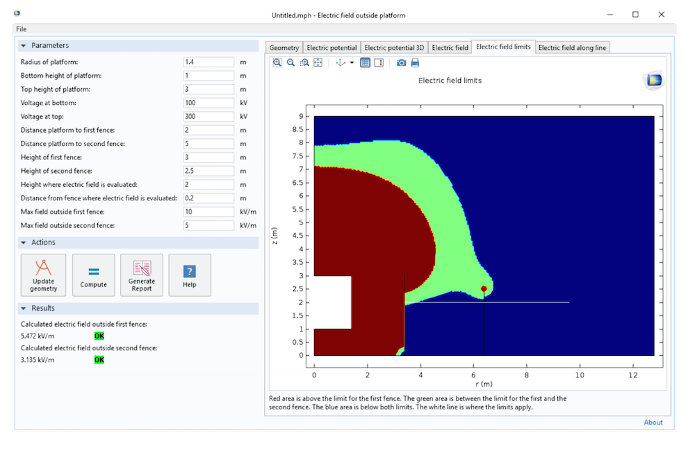
The electric field calculation app. Image by Nils Lavesson and taken from his COMSOL Conference 2016 Munich paper.
Along with access to help, users also have the option to generate a report that includes the calculation’s input parameters, plots, and results — all with just a simple click of the Report button. This makes it possible to efficiently document individual simulation studies throughout the entire design process and easily communicate each set of results to a larger group.
Comparing 2D and 3D Simulation Results
After completing the design of the app, Lavesson created a 3D model in COMSOL Multiphysics based on the same analysis and compared the results between the two studies. For this purpose, he used a common example geometry. While it wasn’t necessary for this analysis, it’s possible to design an app using this 3D model.
This geometry features a 2×2 square tower that is 3 m tall, with voltage increasing linearly from 100 to 300 kV. Surrounding the tower are two fences, one that is 3 m tall and another that is 2.5 m tall. These fences are 2 m and 5 m away from the tower, respectively. The evaluation of the electric field is performed at 2 m above the ground.
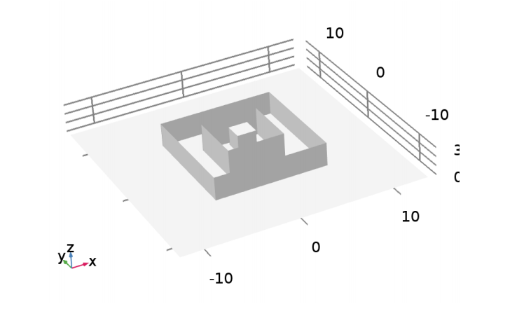
The 3D geometry. Image by Nils Lavesson and taken from his COMSOL Conference 2016 Munich paper.
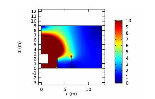
A cut is made at the center of the platform of the full 3D geometry. The cut includes the maximum field outside the fences because of symmetry. Outside the first fence, the maximum field is evaluated as 4.6 kV/m. Outside the second fence, the maximum field is evaluated as 2.5 kV/m.
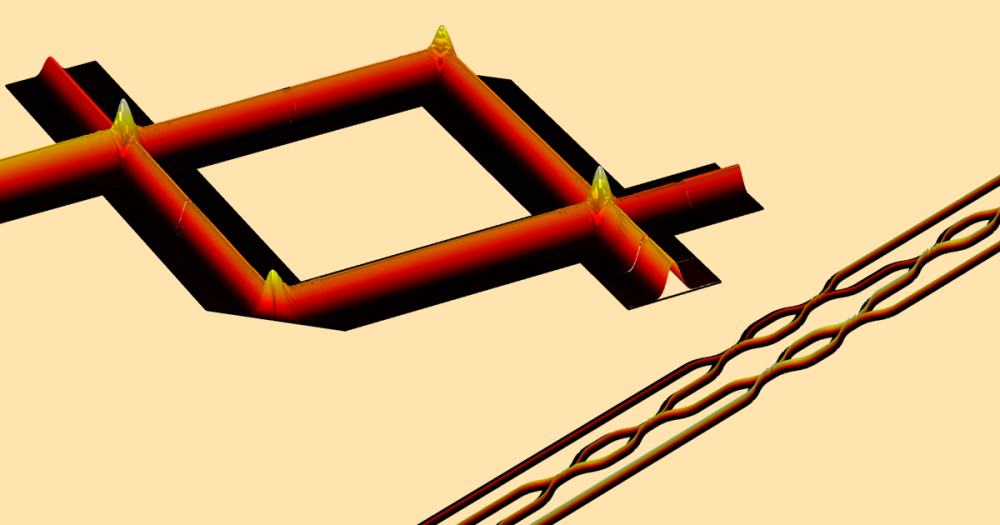
Electric field calculations outside the electrical installation tower along the cut plane in the 3D geometry. Image by Nils Lavesson and taken from his COMSOL Conference 2016 Munich paper.
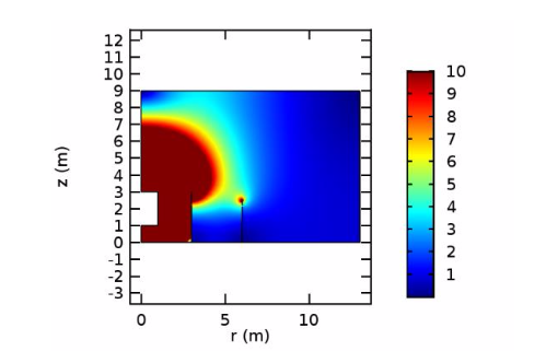
This same analysis is repeated using the app. Using the same simplified geometry described above, a cylinder is used to approximate the tower, with the radius defined as half the diagonal distance of the tower. The distances to the fences are defined as the respective minimum distances. When plotting the electric field along the 2D plane, the results show that the maximum field is 5.5 kV/m outside the first fence and 3.1 kV/m outside the second fence.
Electric field calculations outside the electrical installation tower for the 2D geometry included within the app. Image by Nils Lavesson and taken from his COMSOL Conference 2016 Munich paper.
For the 2D approximation, you’ll notice that the values are slightly larger than they are for the 3D geometry. This is intentional with the use of the platform’s largest dimensions and minimum distances to the fence. Such an approach ensures that any design that falls within the electric fields for the 2D geometry also meets these requirements when a 3D simulation is performed.
Apps Offer an Optimized Approach for Analyzing Electrical Installation Designs
As preliminary 2D simulations help to ensure that designs are not far from the optimal state, the electric field app has the potential to be quite useful to design engineers down the road. If greater accuracy in optimization is desired, a full 3D simulation can be performed to complement the app’s simulation results. As highlighted in the simulation research above, good agreement is found between the results from the app and those from the sample 3D geometry.
While this specific app is limited to a class of particular geometries, the flexibility of the Application Builder makes it possible to build similar apps that can address other geometrical configurations. Extending the scope of these simulation capabilities provides a way of optimizing design processes for a wide range of electrical installations in the years ahead.
Explore Further Uses of Building Apps to Improve Design Processes
- Read the full COMSOL Conference paper: “An App for Calculating the Electric Field outside of Electrical Installations“
- See how another team at ABB built apps to more efficiently model transformers: “ABB Minimizes Transformer Hum with Simulation“
- Find out what some COMSOL® software users who are already building apps have to say: “Multiphysics Simulation Is More Accessible with the Application Builder“


Comments (0)