Building 2D Geometry
Geometry models can be created within the COMSOL Multiphysics® software environment using the built-in geometry modeling features and functionality. In this article, we will begin by focusing on sketching in 2D directly in the Graphics window. We will then show how to edit with Sketch mode and how you can add Object Primitives directly to your geometry. After you have learned the basics of building 2D geometries, we will show the process using an example model. The end of this article includes modeling exercises for practicing what you will learn here.
Adding Components for Sketch Mode
One way for you to draw and edit geometry is by using Sketch mode. Drawing can be done right in the Graphics window with this feature. This is primarily how we will be building geometries in this article. To begin sketching, you will need to add a 2D component or a work plane to your model. There are several methods for adding components to your models. If you are starting a new model, you may want to use the Model Wizard to add the type of component, physics, and study you want to begin with.
While you are building your model, components can be added from the Home toolbar or the context menu. You can add multiple and different types of components to the Model Builder this way.
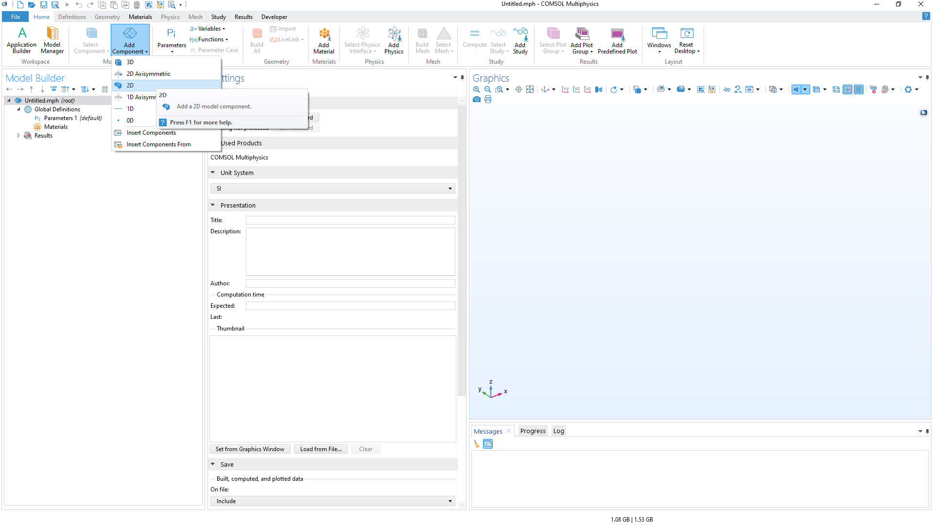 The COMSOL Multiphysics UI with the Add Component button selected in the Home toolbar, and then 2D selected from there.
A 2D component is selected in the Home toolbar and will be added to the Model Builder.
Note that 3D geometries often use work planes, which follow the same principles as shown here in 2D. Work planes can be added from the Geometry toolbar, and then the Plane Geometry can be sketched.
Drawing with Sketch Mode
To begin sketching the geometry for your first component:
- Select the Sketch toolbar
- Select the type of shape you want to draw
- Click and drag in the Graphics window as necessary to create the shape
You can also right click in the Graphics window, while Sketch mode is on, to show the context menu and select the type of shape you want to draw. Sketch mode can be toggled on or off using the respective button in the Sketch toolbar. If your version of COMSOL Multiphysics® does not include Sketch mode, you may need to upgrade to a more recent version of COMSOL Multiphysics®.
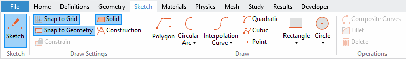
The Sketch toolbar with Sketch mode on. The toolbar is available under the Geometry or Sketch ribbon tabs for 2D or 3D model components.
To create a new 2D sketch, you can simply interactively draw a wireframe rendering of your geometry. Once you leave Sketch mode, by turning it off or leaving the Geometry node in the Model Builder, your sketch will become a 2D object. By default, a closed geometry will become a solid object, whereas an open geometry will become a curve object.
 The Graphics window with an open geometry, resulting in a curve object.
 The Graphics window with a closed geometry, resulting in a solid object.
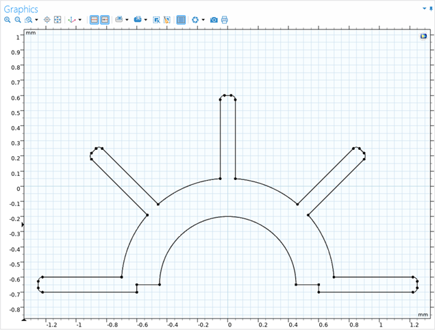
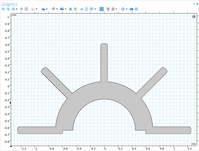
An example of the Graphics window when Sketch mode is on (left) and off (right).
Composite Curves
In COMSOL Multiphysics®, you can create objects with multiple types of edges by forming a composite curve. The Composite Curve feature is automatically added to your geometry sequence when you draw a series of connected edges. Connected polygons, curves, and arcs can be manually selected and organized within new or existing Composite Curve features. The selections can be made by holding Ctrl and clicking the edges in the Graphics window or the Model Builder window via their nodes. When they are selected, you can choose Composite Curve by right-clicking or from the Operations section of the Sketch toolbar. The connected yet standalone curve objects that were selected are then assembled into a single object.
Correcting Sketches
If you make a mistake while sketching, it is simple to make the correction. There are multiple ways to fix a sketch. If you catch a mistake while sketching an object, you can click the drawing tool you are using to stop where you are. A standalone object will be canceled and a composite curve will be finished. Sections of a composite curve can be deleted by clicking to select them in the Graphics window and using the Delete button. Two or more connected composite curves can be also be combined in the model tree to help keep your model organized.
Editing with Sketch Mode
Once you have sketched an object there are different options you can use to edit it. Sketched objects can be edited in the Settings window or the Graphics window. Values for various properties of the object can be entered in the Settings window, such as the dimensions or position. Alternatively, by clicking and dragging on the object, its edges, or vertices in the Graphics window, the size, shape, or position of your object can be adjusted. You can hold the Ctrl and/or Shift key while dragging your mouse to change how other geometric entities move in your sketch.
It may be necessary to modify objects manually in the Settings window to edit your geometry. Editing in the Settings window enables you to exactly specify the dimensions required. When objects are selected in the model tree in the Model Builder window, the Settings window will show information for that object, such as the coordinates, dimensions, and rotation angle, among other properties. Objects can also be selected by double-clicking the object in the Graphics window — with this, the associated node and Settings window will open. The approach utilizing the Graphics window can help you find the correct node for an object when you are working with a complex model geometry.
Guidelines and Indicators
There are many visual indicators in the Graphics window while in Sketch mode. For instance, bold grid are visible by default at the x– and y-intercepts, providing a quick reference to grid origin.
 The Graphics window with bold grid lines.
The Graphics window, displaying bold grid lines at the origin upon enabling Sketch mode in the geometry.
Green grid lines will appear when any vertex is moved in your model geometry to align with other points in your geometry. These same type of lines appear while sketching new objects and are useful while sketching or editing because they make it simple for your objects to reference their relative position to each other.
When editing the point coordinates in the Settings window for certain geometric primitive features, such as polygons or interpolation curves, a red circle will identify the corresponding point in the Graphics window. This helps to confirm which points you are editing.
2D Object Primitives
Various built-in geometric shapes can be selected and added to your geometry sequence from the Geometry toolbar. The properties for these 2D geometric primitives can then be edited through the Settings window, and then be built. You can also still interactively edit these shapes through the Graphics window. These objects can be then be combined with other geometry operations to form your final geometry.
Tutorial of 2D Sketching
Now that we have gone over the basics of building 2D geometry with Sketch mode in COMSOL Multiphysics®, we will go through an example model step by step. The model we will be building is a cross section of a light bulb, which we can model in 2D even though the object is 3D. In the case of a lightbulb, we should have axial symmetry, and the results of a 2D simulation can be revolved to show results in 3D. This will take less time to model and compute a solution. You can follow along with the video below and refer to the written step-by-step instructions included with the Light Bulb Geometry tutorial model in the Application Gallery. There, you can also find the MPH-file for the model.
Modeling Exercises
In order to put into practice what you have learned through this article, we have provided several self-guided modeling exercises. Use the images and MPH-files included as a reference while you sketch the geometry yourself to test your knowledge. When needed, you can check the solution files attached to this article to see how you did. The Compare tool in the software can be used to identify the differences between the solution and your sketch. It is important to note that there are multiple ways to create the geometries, so your geometry could be correct but simply created in a different manner.
Circulator
Open the circulator geometry file in COMSOL Multiphysics®. Then, use the features shown in this article to sketch over the imported geometry. You will have been successful in this exercise if you were able to use the tools to copy the imported geometry by hand. You can check how the original geometry was created with the solution file attached to this article.
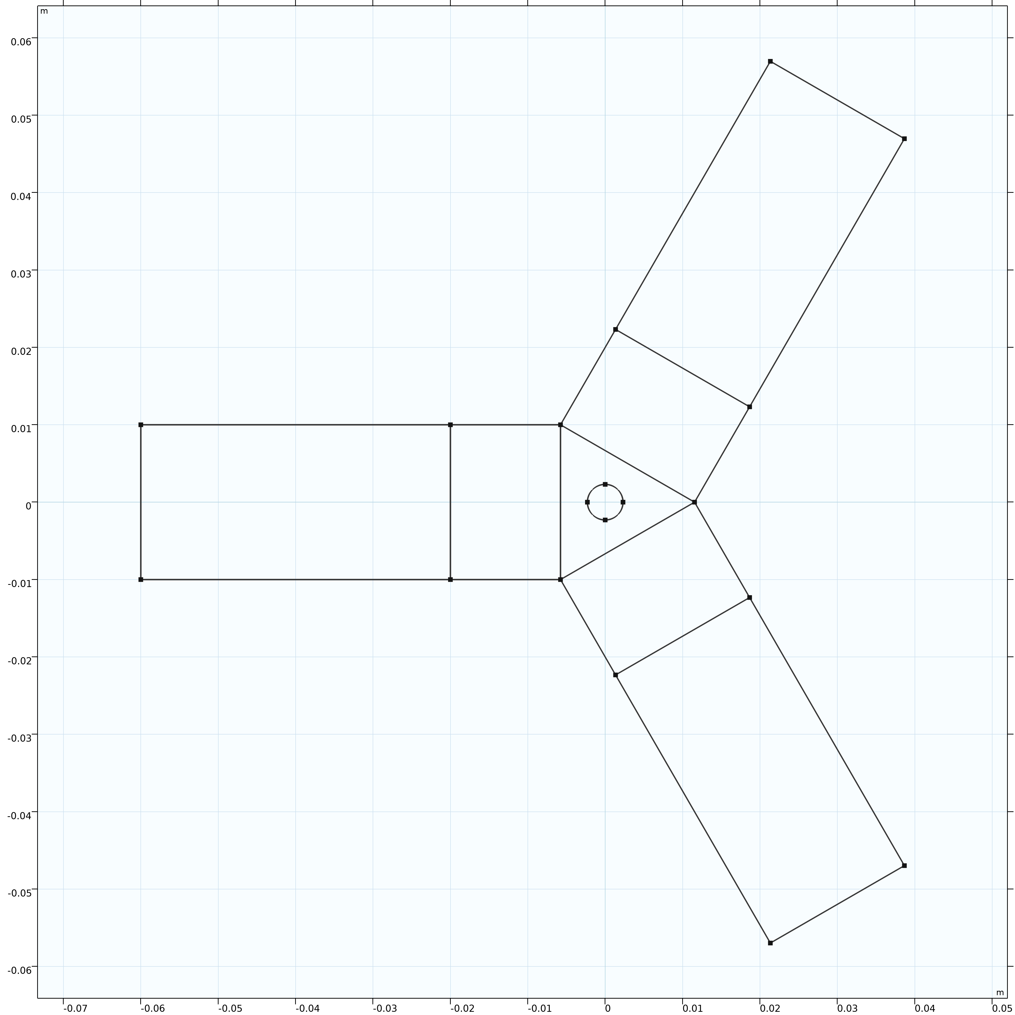 A sketch of the circulator geometry.
Landing Gear
Observe the shape of the model, made to look like landing gear, in the image below, and determine how you may most efficiently sketch it. The wheels should be 0.3 m in diameter, and the structure should have a uniform thickness of 0.1 m. Focus on making the shape of the model and remember that the dimensions can be adjusted afterward. There are two solution MPH-files attached that outline just a couple of the ways the geometry for this model could have been sketched. You can refer to the Application Gallery entry for the landing gear model to learn more.
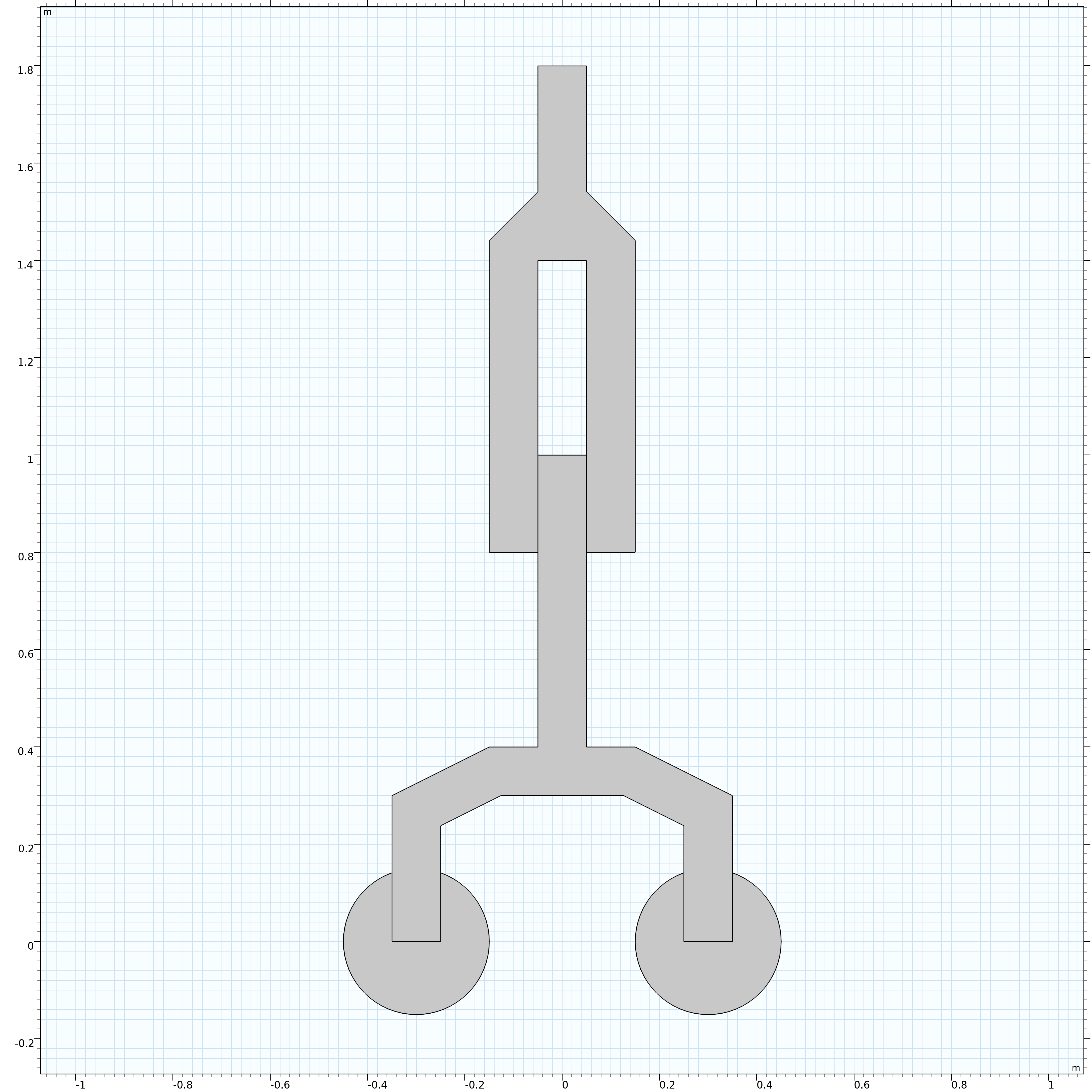 A sketch of the landing gear model.
Abstract Geometry
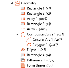
Model this abstract geometry using the images below of the dimensioned sketch and the built geometry. The abstract geometry exists only to practice what you have learned in this article. If you need a hint, reference the geometry sequence to see what features were used to create the geometry originally. You can also compare your result with the attached solution to see how the features were used.
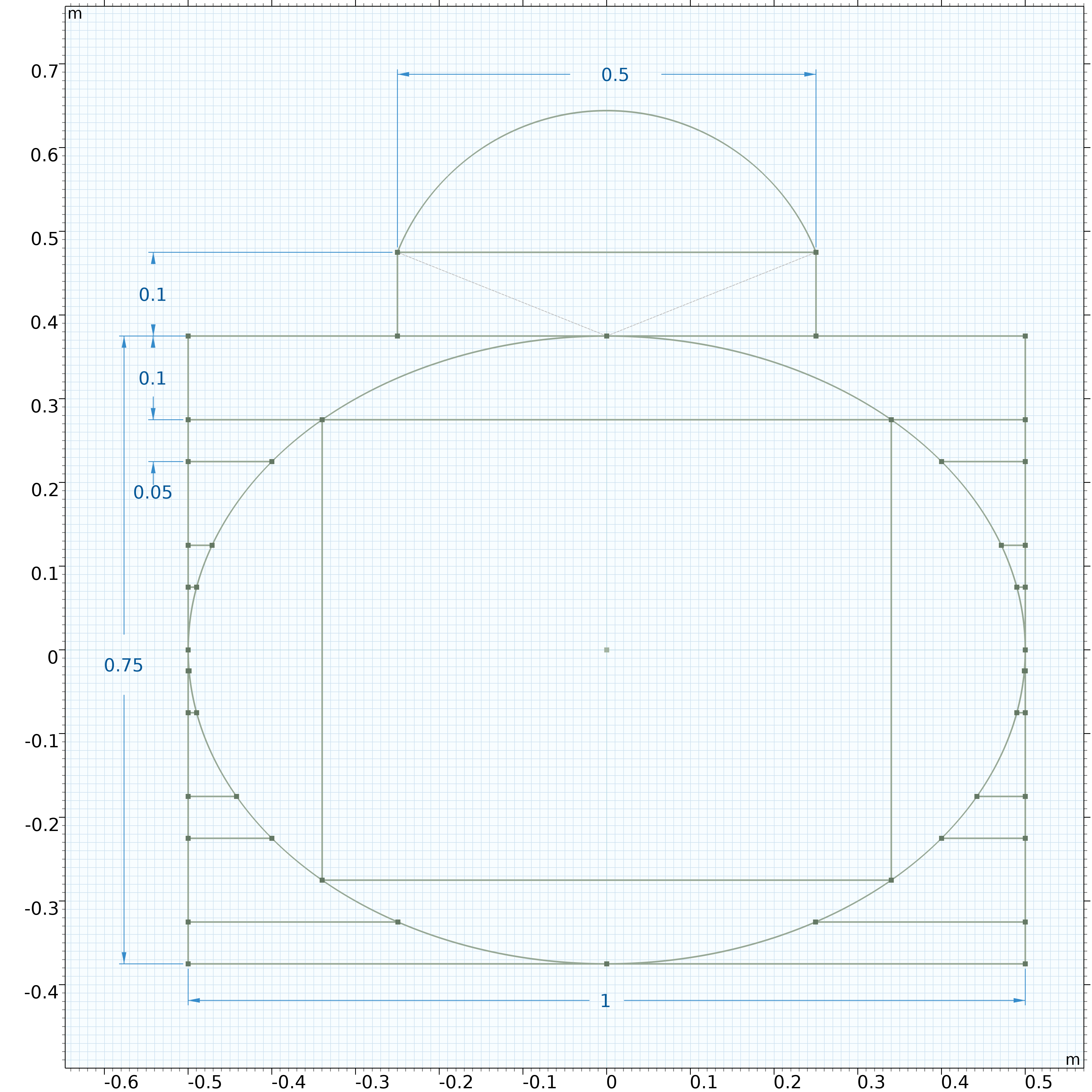 An abstract geometry in Sketch mode, with the dimensions labeled.
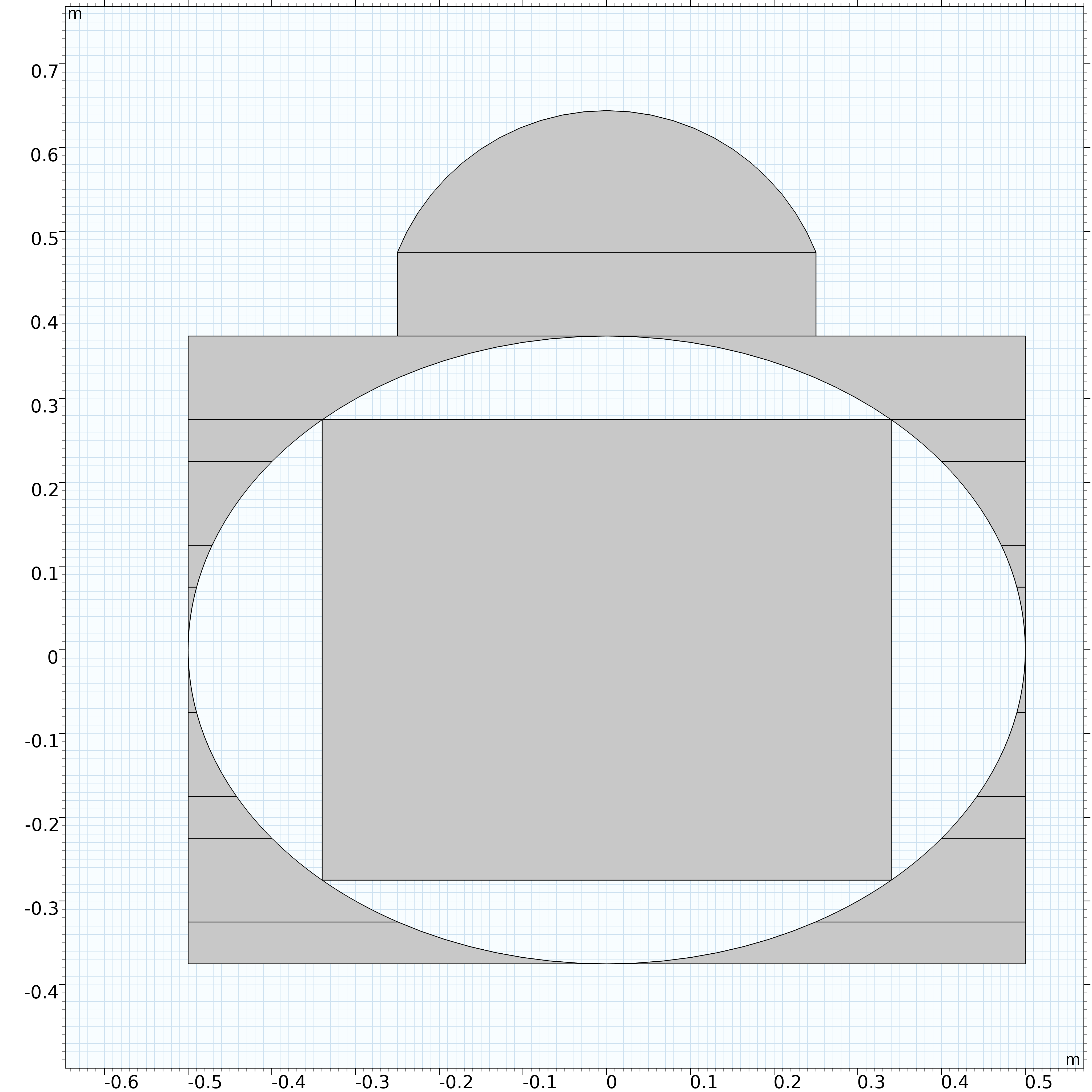 The geometry with the objects built outside of Sketch mode.
An abstract geometry shown in Sketch mode, with the dimensions displayed. Right: The geometry with the objects built outside of Sketch mode.
The Design Module
Additional functionality for building geometry in COMSOL Multiphysics® is included with the Design Module. If you would like to learn more about the features included in the Design Module, such as constraints, dimensions, CAD import functionality, or standard and Boolean CAD operations, we recommend that you check out the Design Module in our product suite and read our blog post "How to Use the Sketch Tools in COMSOL® to Draw 2D Geometry".
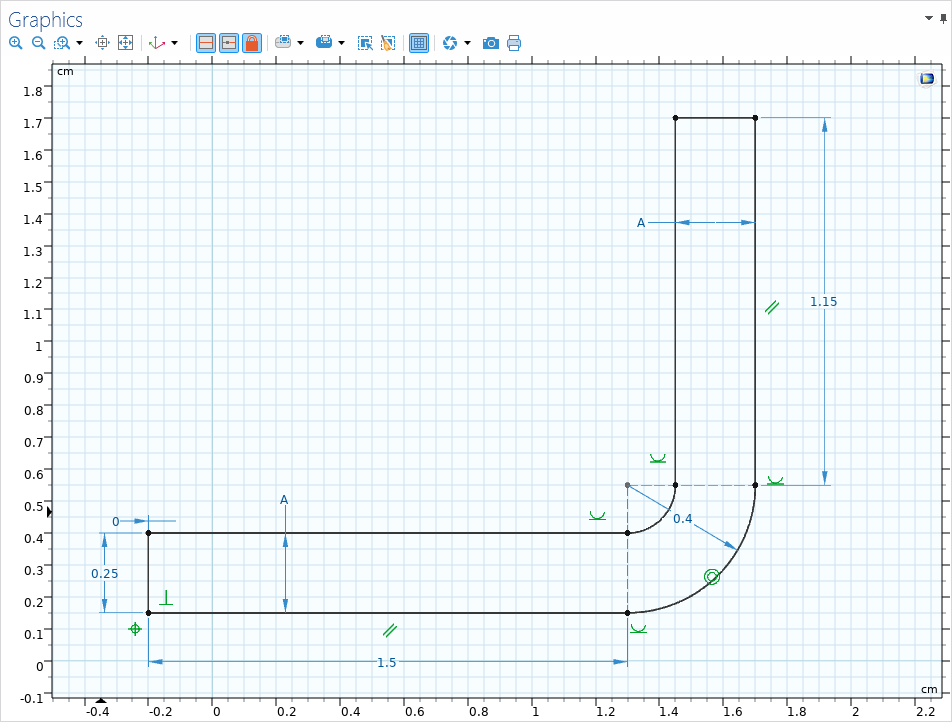 An example geometry in the Graphics window showing the dimensions.
A well-defined example geometry using constraints and dimensions.
An example geometry in the Graphics window showing the dimensions.
A well-defined example geometry using constraints and dimensions.
Further Learning
If you are looking for more materials to help hone your 2D-geometry-building skills in COMSOL Multiphysics®, there are a few resources we recommend:
- The Effective Diffusivity in Porous Materials tutorial model
- The Axisymmetric Twist and Bending tutorial model
- Our Utilizing Geometric Measurements in COMSOL Multiphysics® video to learn about the Measure tool, which can be used to measure geometric quantities in your model
Note that the PDF files for the tutorial models often include content beyond instructions for building the geometry. For the models listed here, we recommend referring to the instructions specific to building the geometry and practicing them using the capabilities discussed here.
Submit feedback about this page or contact support here.