How to Create 2D Geometry from Cross Sections of 3D Designs
COMSOL Multiphysics® contains many specialized features for creating specific types of geometry, such as those that enable you to create 2D geometry from 3D objects by cutting the solid using a plane. In this article, we will discuss the use cases for doing this, the advantages of implementing this approach, and demonstrate how to do it.
Use Cases and Functionality
Taking a cross section from a 3D geometry and then using that cross-sectional slice in a 2D model is particularly useful when building models that involve any of the following elements:
- Symmetric or axisymmetric 3D geometries, in which you can create a 2D model based on your 3D model and obtain significantly faster solutions for the same geometry
- Thin-walled parts, in which you can use the plane stress assumption for your 2D model
- Long parts, in which you can use the plane strain modeling assumption for your 2D model
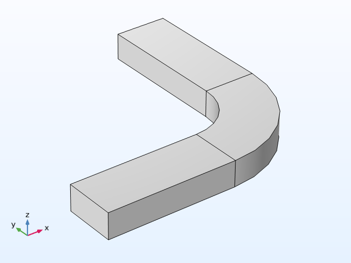 A 3D model of an h-bend waveguide.
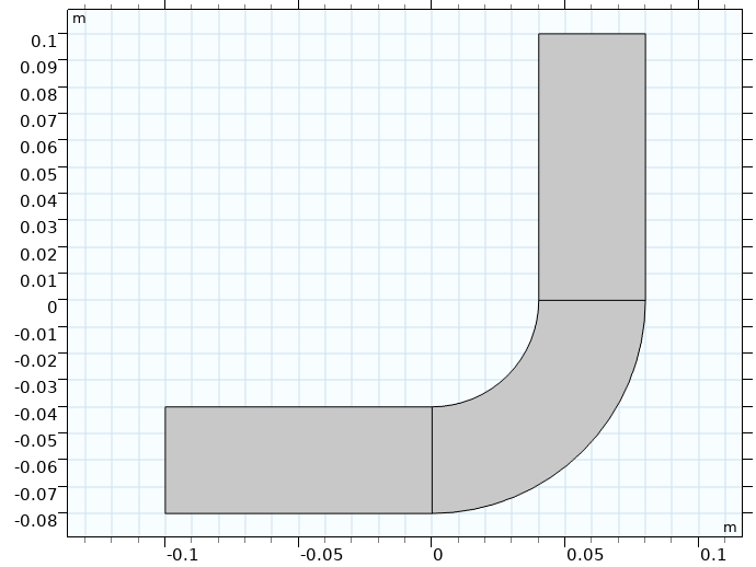 The 2D cross-sectional geometry of the h-bend model.
The 3D geometry (left) and 2D cross-sectional geometry (right) for a model of an h-bend waveguide. The physics of the model make it possible to set up and compute in 2D.
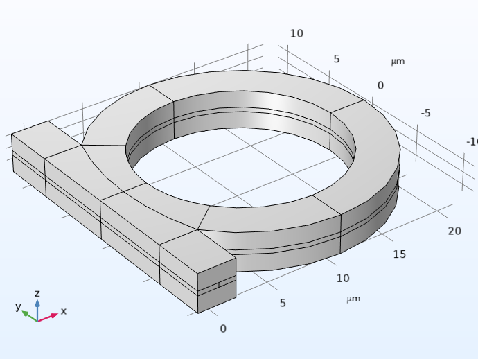 3D geometry of an optical ring resonator notch filter.
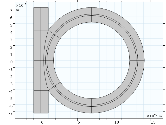 The 2D cross-sectional geometry of the optical ring resonator notch filter model.
The 3D geometry (left) and 2D cross-sectional geometry (right) for a model of an optical ring resonator notch filter. The 2D model is used to investigate different designs for the optical ring resonator before any 3D model simulations are computed.
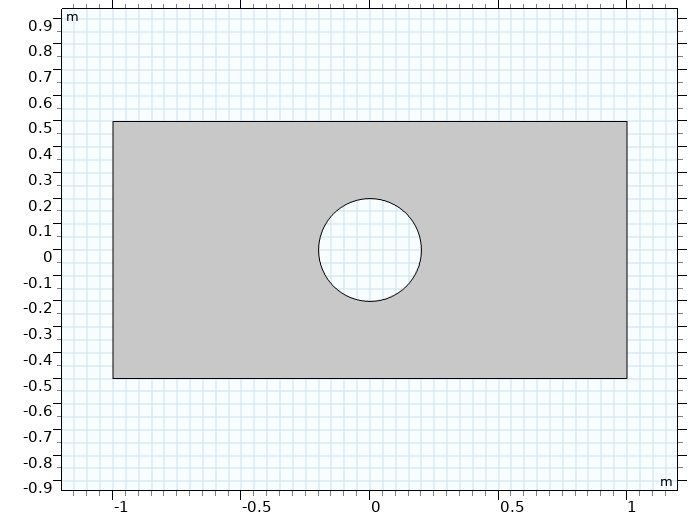 A 2D rectangular plate model with a hole in the center.
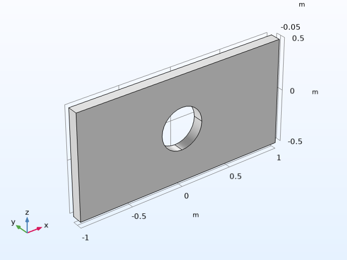 The rectangular plate model in 3D.
A model of a rectangular plate with a hole in the center. The plate is modeled in 2D using a plane stress assumption (left) before turning to model the full, 3D model (right).
Using this approach is also helpful for developing large or complex 3D models. By taking advantage of 2D model approximations when possible, you can more quickly and easily investigate specific aspects of your simulation, all before applying them to the 3D model. This could include analyzing any small or complex geometric features, material property values, physics settings, multiphysics couplings settings, mesh settings, or solver settings.
Process
In COMSOL Multiphysics, cutting through a solid using a plane is done in two steps. First, add a work plane to the geometry for your 3D model component. The work plane needs to be placed so that the appropriate cross section can be obtained from where the work plane cuts through the 3D solid object.
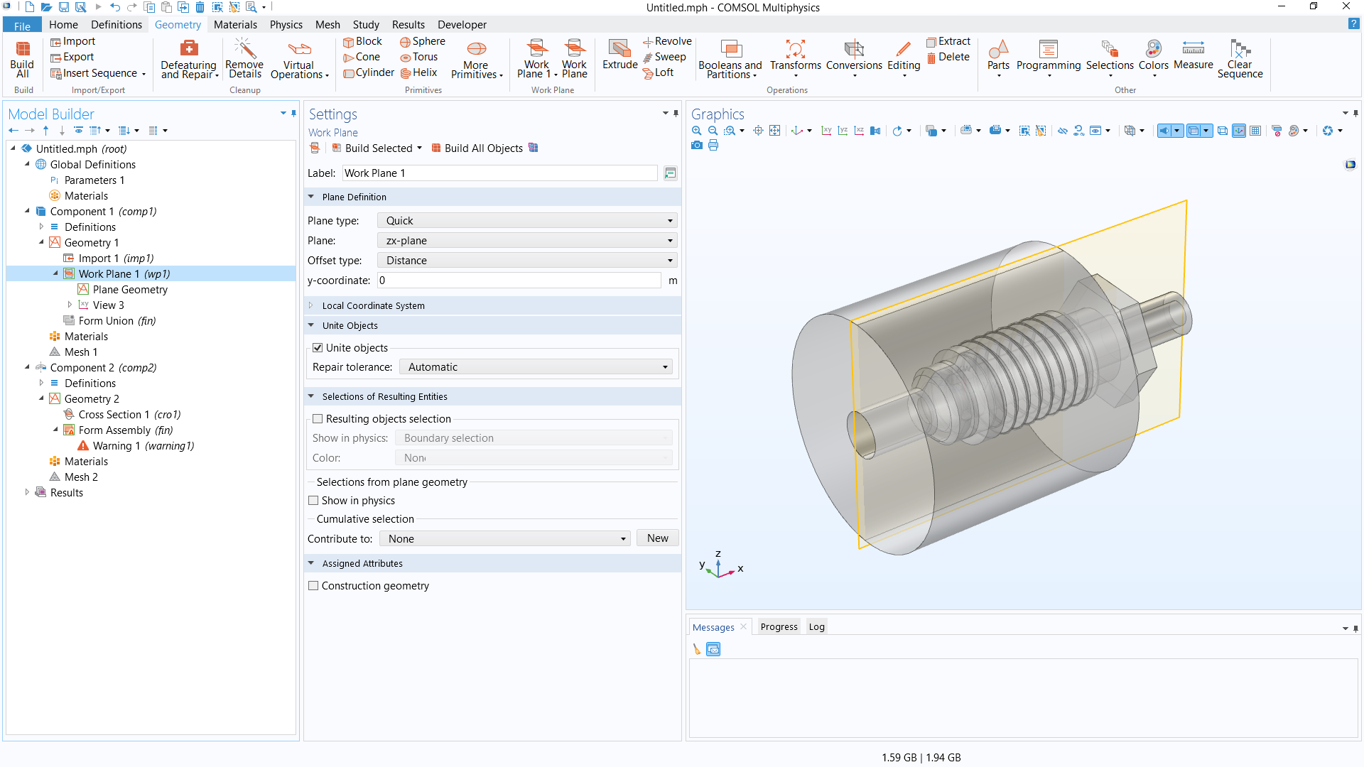 The COMSOL Multiphysics UI showing the Model Builder with the Work Plane feature selected, the corresponding Settings window, and the Graphics window with the 3D geometry of a pipe fitting model.
The 3D model geometry for a pipe fitting, with transparency enabled to see the inside. A work plane is added in the xz-plane along the center of the design, from which the cross section is obtained.
Next, add a second model component, either 2D or 2D axisymmetric, and subsequently add a Cross Section geometry operation. With this, you obtain the cross section from the work plane defined previously in the 3D model component. (You can also do this with the Projection operation, but note this functionality requires the Design Module.)
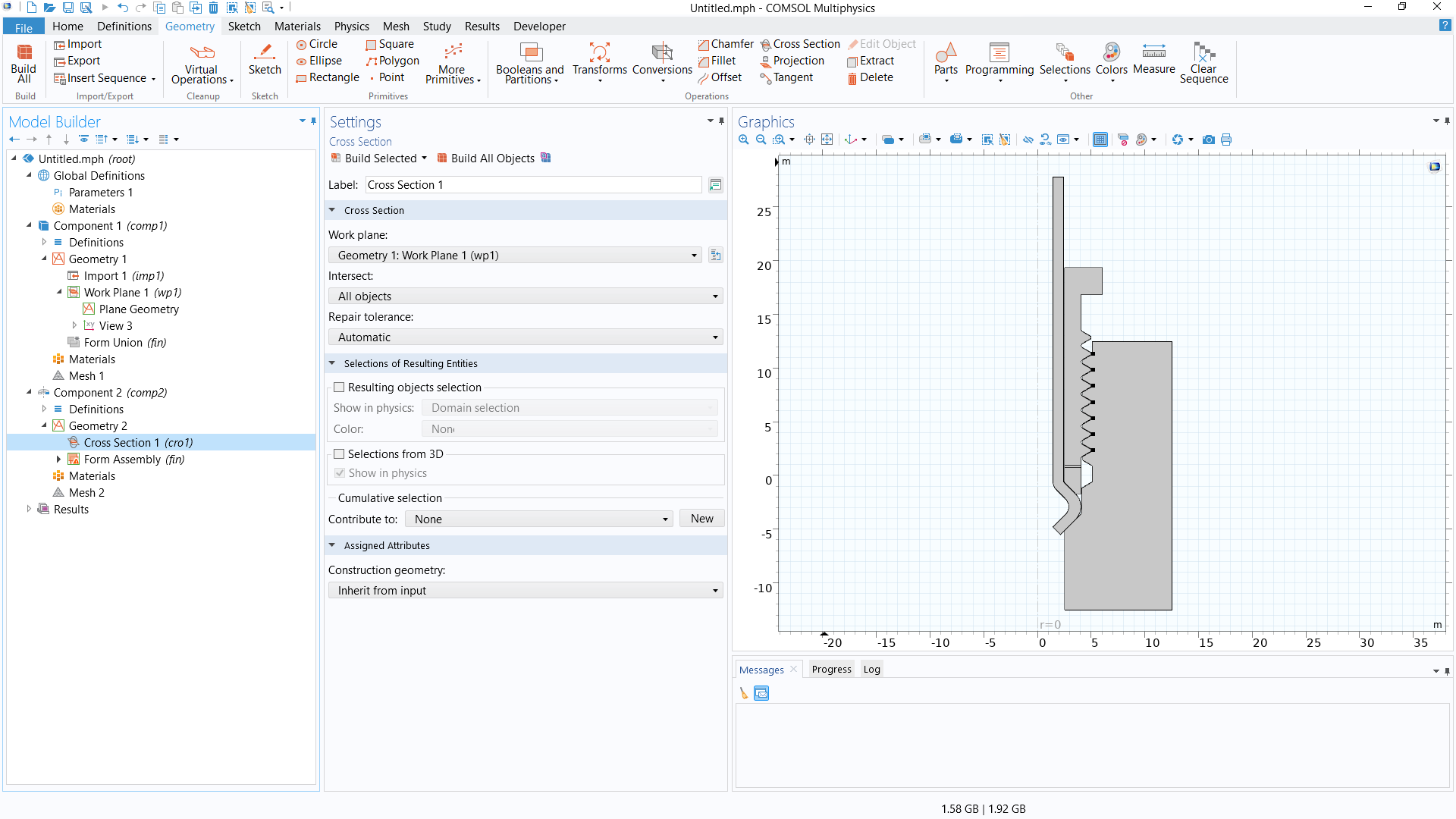 The COMSOL Multiphysics UI showing the Cross Section feature selected, the corresponding Settings window, and the Graphics window with the 2D axisymmetric geometry of the pipe fitting model.
The cross section used to create a 2D axisymmetric model of the pipe fitting.
Watch the video below and follow along step-by-step in the software using the exercise files to learn how to convert 3D geometries for use in 2D model components. We also discuss how it may be necessary or optimal for you to prepare your 3D geometry so that you can obtain an appropriate, representative 2D cross section. This process largely depends on the design and the features contained therein.
Tutorial Video: Create 2D Geometry from Cross Sections of 3D Designs
Modeling Exercises
Demonstrate the knowledge you have gained from this article by putting it into practice with the follow-up modeling exercises listed below. The directions provided are intentionally generalized to encourage self-guided problem solving. You can manually check your implementation with the solution model files provided here or use the comparison tool to identify any differences.
Recommended exercises:
- For the shell-and-tube heat exchanger model geometry (MPH-file), determine how to convert the 3D model into 2D to obtain the geometry pictured below
- For the corrugated circular horn antenna model geometry (MPHBIN-file), create a geometry that can be used in a 2D axisymmetric model of the design
- For the ball check valve model geometry (MPHBIN-file), create a geometry that can be used in a 2D axisymmetric model of the design
For the shell-and-tube heat exchanger model geometry, you can download the MPH-file from the linked text. For the MPHBIN files, download the files linked above and then import them into the software.
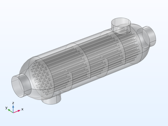 The 3D geometry of a shell-and-tube heat exchanger model.
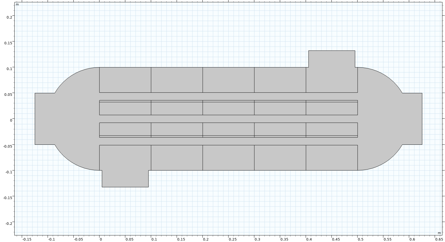 The 2D geometry of the shell-and-tube heat exchanger model.
The 3D model geometry for a shell-and-tube heat exchanger (left) and the geometry used for a 2D model of the design (right).
Further Learning
To learn more about reducing your model geometry from 3D to 2D, see our Learning Center article "Using Symmetry to Reduce Model Size". In the Application Libraries, there are also several tutorial models that simulate a device or system in both 2D and 3D, which you can inspect further to see how the 2D approximation for the model was implemented. Available models (and their corresponding application area) include:
- Out-of-Plane Heat Transfer for a Thin Plate (Heat transfer)
- Mass Transfer from a Thin Domain (Chemical)
- Convection Cooling of Circuit Boards (Fluid flow)
- Permanent Magnet Motor in 2D (AC/DC)
- Permanent Magnet Motor in 3D (AC/DC)
- H-Bend Waveguide (RF)
- Solidly Mounted Resonator 2D (MEMS)
- Solidly Mounted Resonator 3D (MEMS)
Submit feedback about this page or contact support here.