3-D Modeling of Stresses and Strains in Accessory Carpal Bone Under Maximum Compressive Loading
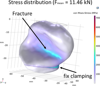
When treating fractures of the accessory carpal bones in horses, it is important to understand the forces that implants (screws and plates) must withstand. The etiology of the fracture is not fully understood, but their high incidence during exercise suggests a relation to biomechanical forces. Detailed descriptions of the intact and fractured accessory carpal bone's morphology and functional anatomy are lacking, which is crucial for stable fracture fixation. Therefore, the aim of this study is to create an FEM model for simulating the optimal selection and placement of implants. The primary focus of this work is to create and validate the model through an FEM study in order to calculate the stresses and strains that occur in the accessory carpal bone under maximum compression (force-to-failure). So far, the maximum strength of this bone was not investigated. In the literature, the authors hypothesize that the bone has a predetermined breaking point. To determine the maximum strength, experimental compression (force-to-failure) tests were conducted on equine accessory carpal bones (n = 8) using a four-column testing machine. Subsequently, an FEM model was built in COMSOL Multiphysics® (Nonlinear Structural Materials Module). CT scans were utilized to convert the morphology of the accessory carpal bone into a step file which was then loaded into COMSOL Multiphysics®. The boundary conditions corresponded to those from the experimental uniaxial compression tests (Figure 1). The obtained force-to-failure values were used as boundary loads. For the description of the accessory carpal bone, a hyperelastic material model according to neo-Hookean was defined. Furthermore, a mesh convergence study was performed to exclude the influence of the mesh. Since the material parameters are unknown, stresses, deformations and strains were determined using varying moduli of elasticity (E = 4 GPa – 30 GPa) and a constant Poisson’s ratio of v = 0.4. The results from the compression tests revealed force-to-failure values of 11.46 +/- 2.49 kN. The calculated stresses ranged from 500 – 3000 MPa, depending on the modulus of elasticity used. The highest stresses occurred both in the bone fracture, typically in a vertical plane between half and two-thirds of the bone, and in the area where the bone is clamped in the testing machine (Figure 2). The simulated deformations behavior matched those obtained from the experimental compression tests. Thus, the comparison of the simulated deformations with those from the experimental tests helped narrow down the elastic modulus range (E = 4 GPa – 6 GPa). The simple FEM model developed in this study can be used for initial investigations into understanding the etiology of the fracture and for the selection and placement of implants for stable fracture fixation of the accessory carpal bone. Future work will focus on improving the model. This includes determining the material properties of the bone and employing more complex material models. Likewise, fracture formation can be simulated, which is not considered in this model.
Download
- Reuter_6431_poster.pdf - 1.09MB
- PKKV_Paper_2023-09-21_final.pdf - 1.02MB