

As much as we would like to think that finite element analysis (FEA) is the be-all and end-all of simulations, it’s not true. There is also a camp of engineers out there that model integrated circuits and similar systems. These are based on different physics and equations than what FEA typically solves for. Yet, as is happening more and more in the world of virtual prototyping, the two types of simulations are converging. Now they need to integrate with each other. It is with this in mind that we released a new product that helps these electrical and electronics engineers move between these two worlds.
A big reason for the disconnect between finite element and, say, integrated circuit (IC) modeling is the file formats used for defining geometries. I previously blogged about this when I described the differences between Computer-Aided Design (CAD) and Electronic Computer-Aided Design (ECAD), and how they both relate to FEA. FEA is useful for the manufacturers’ ICs because it is used to simulate, verify, and optimize many of the physical behavior such as thermal stresses, capacitance and inductance, of the individual components that make up these circuits. Our new product converts the ECAD file’s data to a CAD geometry on which the simulations can be run.

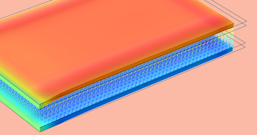
The extraction of inductance and capacitance can be done from a model of a planar transformer, made up of a Printed Circuit Board (PCB) and ferrite core. To achieve the geometry, an ECAD file was imported via the ECAD Import Module, which read the layout and automatically created a 3D geometry model.
The ECAD Import Module imports NETEX-G, GDS-II, and ODB++(X) 2D layouts and, making use of the metadata that comes with the ECAD file, automatically converts them to 3D CAD geometries. There are other parameters in these ECAD files that can also be manipulated, such as, selecting which subset of nets, cells, and layers you want to import, controlling layer thicknesses and the geometric representation of bond wires, and including dielectric regions.
Some of this functionality has already been available to COMSOL users, particularly for those wanting to extract electromagnetic behavioral data from an IC component.
ECAD files are also used by engineers that design MEMS systems and want to simulate electronics cooling. They will also find this a useful tool. And if you have the CAD Import Module or one of the LiveLink® products, then the 3D geometry can be converted and manipulated in the Parasolid® file format.


Comments (1)
kherbouche fouad
April 9, 2013Numerical Modeling of Electrostatic Precipitators